policyrouting
Getting around TV App Geo-Blocking
Executive Summary
This blog post explains how Policy Routing on a Linux server together with commercial VPNs to other countries can help you to put your client devices (TV, smartphones) logically into the internet of other countries in order to get around geo-blocking.
Background
The idea or merely, the need for this approach, surged when I installed an app of a Portuguese TV provider and could not even watch the news journal due to geo-blocking. Additionally, I wanted to have a comfortable solution with which I can switch the TV to different countries while I am sitting in my TV chair with my smartphone at hand 😁.
Preconditions
In order to use the approach described here, you should:
- … have access to a Linux machine which is already properly configured on its principal network interface (e.g., eth0)
- … have the package openvpn installed on the Linux machine (preferably from a repository of your Linux distribution)
- … have access to a commercial VPN provider allowing you to run several parallel client connections on the same machine
- … have knowledge of routing concepts, networks, some understanding of shell scripts and configuration files
- … know related system commands like sysctl
- … familiarize yourself with [1], [3], [4], [5]
Description and Usage
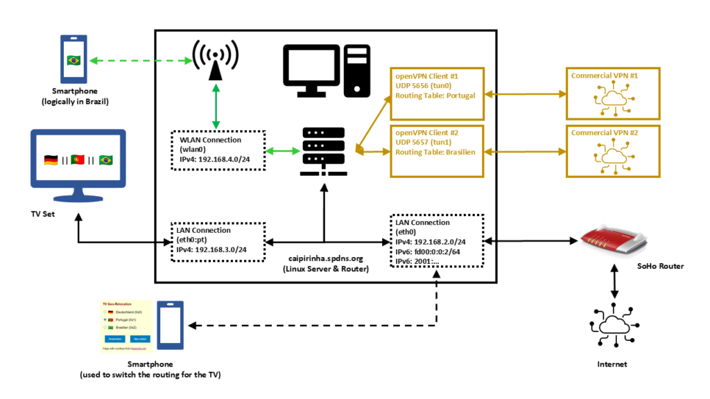
In this setup, we have a full-blown SoHo Linux server on an internal network 192.168.2.0/24 that is also used by all other devices in the same home. Subsequently, we will connect this Linux server via a commercial VPN to two endpoints, one endpoint in Portugal and one endpoint in Brazil. We will also create two additional networks for our SoHo environment:
- 192.168.4.0/24 will be spread via WLAN (WiFi) and will constantly logically be “in Brazil”. This network can simply be selected by a smartphone at home, and the smartphone will have a Brazilian internet connection while still being able to access all resources in the home network.
- 192.168.3.0/24 will an overlay on our wired SoHo network. The TV set will be the only client in this network. We will make the endpoint of this network selectable, that is, one shall be able to select whether this network is in Germany, in Portugal, or in Brazil.
That setup is suited to my personal preferences, but of course, after having read through this article, you will know sufficiently to suit the setup to your preferences and demands.
OpenVPN Client Configuration
For the setup described below, we need two client VPN connections, to Portugal and to Brazil. As I do not have infrastructure outside of Germany, I use a commercial VPN provider, in my case this is Private Internet Access®. However, there are several commercial VPNs that you can also use; the important thing is that they allow several active connections from one device and that you can configure and adapt the VPN configuration file, preferably for an openvpn connection (as this will also be described here). The client configuration files listed here use UDP, a split-tunnel setup and also contain all the necessary certificates in one file. The login credentials are stored in another file named /etc/openvpn/pia.login. The certificates of the configuration files have been omitted here for readability reasons. An important configuration command is route-nopull as it inhibits that we pull (default) routes from the commercial VPN server. After all, we want to specify ourselves which IP packets shall use which outgoing network.
UDP-based split VPN to Portugal
# Konfigurationsdatei für den openVPN-Client auf CAIPIRINHA zur Verbindung nach Portugal mit PIA

auth-user-pass       /etc/openvpn/pia.login
auth-nocache
auth-retry           nointeract
auth                 sha1
client
compress
dev                  tun0
disable-occ
log                  /var/log/openvpn_PT.log
lport                5457
mute                 20
proto                udp
persist-key
persist-tun
remote               pt.privacy.network 1198
remote-cert-tls      server
reneg-sec            0
resolv-retry         infinite
route-nopull
script-security      2
status               /var/run/openvpn/status_PT
tls-client
up                   /etc/openvpn/start_piavpn.sh
down                 /etc/openvpn/stop_piavpn.sh
verb                 3

<crl-verify>
-----BEGIN X509 CRL-----
...
-----END X509 CRL-----
</crl-verify>

<ca>
-----BEGIN CERTIFICATE-----
...
-----END CERTIFICATE-----
</ca>
UDP-based split VPN to Brazil
# Konfigurationsdatei für den openVPN-Client auf CAIPIRINHA zur Verbindung nach Brasilien mit PIA

auth-user-pass       /etc/openvpn/pia.login
auth-nocache
auth-retry           nointeract
auth                 sha1
client
compress
dev                  tun1
disable-occ
log                  /var/log/openvpn_BR.log
lport                5458
mute                 20
proto                udp
persist-key
persist-tun
remote               br.privacy.network 1198
remote-cert-tls      server
reneg-sec            0
resolv-retry         infinite
route-nopull
script-security      2
status               /var/run/openvpn/status_BR
tls-client
up                   /etc/openvpn/start_piavpn.sh
down                 /etc/openvpn/stop_piavpn.sh
verb                 3

<crl-verify>
-----BEGIN X509 CRL-----
...
-----END X509 CRL-----
</crl-verify>

<ca>
-----BEGIN CERTIFICATE-----
...
-----END CERTIFICATE-----
</ca>
Both configuration files call upon scripts (/etc/openvpn/start_piavpn.sh and /etc/openvpn/stop_piavpn.sh) which are executed upon start and upon termination of the VPN. start_piavpn.sh (which needs the tool ipcalc to be installed on the server) populates the routing table Portugal or Brasilien, depending on which client configuration has called the script. It furthermore blocks incoming new connections from the commercial VPNs for security reasons. Normally, you should not experience incoming connections on your commercial VPN (unless this has been wanted and ordered by you), however, I have seen different behavior in the past. Finally, the script start_piavpn.sh sets the correct default route in the corresponding routing table. The script stop_piavpn.sh deletes the blocking of incoming requests. There is no need to delete the previously active default routes from the routing tables Portugal or Brasilien as they will vanish anyway with the termination of the VPN connection. All other configuration options have been discussed in detail already in [1], [2].
start_piavpn.sh
#!/bin/bash
#
# This script sets the VPN parameters in the routing tables "main", "Portugal", and "Brasilien" once the connection has been successfully established.
# This script requires the tool "ipcalc" which needs to be installed on the target system.

# Set the correct PATH environment
PATH='/sbin:/usr/sbin:/bin:/usr/bin'

VPN_DEV=$1
VPN_SRC=$4
VPN_MSK=$5

VPN_GW=$(ipcalc ${VPN_SRC}/${VPN_MSK} | sed -n 's/^HostMin:\s*\([0-9]\{1,3\}\.[0-9]\{1,3\}\.[0-9]\{1,3\}\.[0-9]\{1,3\}\).*/\1/p')
VPN_NET=$(ipcalc ${VPN_SRC}/${VPN_MSK} | sed -n 's/^Network:\s*\([0-9]\{1,3\}\.[0-9]\{1,3\}\.[0-9]\{1,3\}\.[0-9]\{1,3\}\/[0-9]\{1,2\}\).*/\1/p')

case "${VPN_DEV}" in
  "tun0") ROUTING_TABLE='Portugal';;
  "tun1") ROUTING_TABLE='Brasilien';;
esac

iptables -t filter -A INPUT   -i ${VPN_DEV} -m state --state NEW,INVALID -j DROP
iptables -t filter -A FORWARD -i ${VPN_DEV} -m state --state NEW,INVALID -j DROP

ip route add ${VPN_NET} dev ${VPN_DEV} proto static scope link src ${VPN_SRC} table ${ROUTING_TABLE}
ip route replace default dev ${VPN_DEV} via ${VPN_GW} table ${ROUTING_TABLE}
stop_piavpn.sh
#!/bin/bash
#
# This script removes some routing table entries when the connection is terminated.

# Set the correct PATH environment
PATH='/sbin:/usr/sbin:/bin:/usr/bin'

VPN_DEV=$1
VPN_SRC=$4
VPN_MSK=$5

iptables -t filter -D INPUT   -i ${VPN_DEV} -m state --state NEW,INVALID -j DROP
iptables -t filter -D FORWARD -i ${VPN_DEV} -m state --state NEW,INVALID -j DROP
Routing Tables
In order to use Policy Routing, we set up routing tables as described in [1], and we describe these routing tables in /etc/iproute2/rt_tables:
#
# reserved values
#
255 local
254 main
253 default
0 unspec
#
# local
#

240 Portugal
241 Brasilien
The idea here is to direct all IP traffic that shall go to Portugal to the routing table Portugal, and to direct all IP traffic that shall go to Brazil to the routing table Brasilien. The routing table main will be used for all other traffic; it is part of the default configuration of /etc/iproute2/rt_tables.
Local LAN for the TV set
The network that so far has been used on my Linux server has been 192.168.2.0/24, and the corresponding server interface has been eth0. We now need to add one more network to this interface. In order to make that addition permanent and my life easy, I did that via the graphical YaST2 interface.
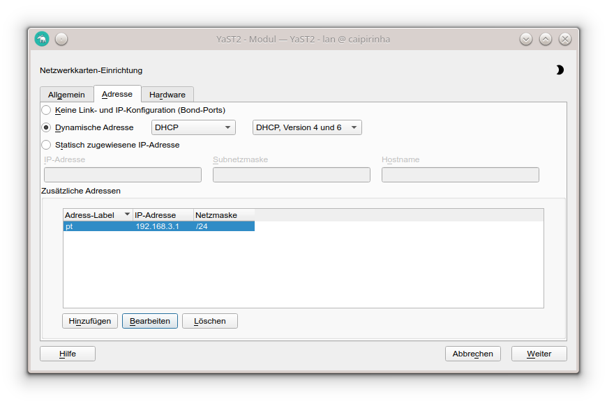
In my case, I chose the address label “pt” (because the original idea was to use this network exclusively for the traffic to Portugal); however, you can choose any label that you wish. While the Linux server usually receives a pseudo-static IP address (192.168.2.3) in the SoHo network 192.168.2.0/24 by the SoHo router (a FRITZ!Box), in our new network 192.168.3.0/24, the server gets the static IP address (192.168.3.1). Clients in this network will consequently require a static IP address configuration; we cannot use DHCP as this network runs on the same physical network infrastructure as the SoHo network 192.168.2.0/24 which already has the FRITZ!Box as DHCP master. In my case, I therefore have configured the TV set (the only client in the network 192.168.3.0/24) with the setup:
- IP address: 192.168.3.186
- Netmask: 255.255.255.0
- Gateway: 192.168.3.1
- DNS server: 192.168.3.1
As DNS I have used the server itself as I have a DNS relay running on the Linux server. If that was not the case, I could also have used 192.168.2.1 which is the address of the FRITZ!Box.
Local WLAN (WiFi) for wireless devices
For the WLAN (WiFi) network I have equipped the Linux server with a PCI Express WLAN card (in my case an old Asus PCE-N10, but I would recommend you a newer one in the 5 GHz band) and attached an external antenna to it. This WiFi card shall act as access point (master). I did not succeed to make that work with YaST2 in conjunction with WPA encryption, and subsequent to my failure, I consulted an Artificial Intelligence (AI) that recommended me to use the package hostapd which needs to be installed on the Linux server. I did so, and after some research and experiments, I came up with a suitable configuration:
/etc/hostapd.conf
# Basis-Einstellungen
interface=wlan0
driver=nl80211
ssid=Querstrasse 8 [BR]
hw_mode=g
channel=1                        # 1-13, vermeiden Sie DFS-Kanäle (52+)
ieee80211n=0                     # Optional für bessere Phones, aber ungünstig bei schlechter Verbindung

# WPA2-PSK (wpa=2 für WPA2 only, TKIP/CCMP für Kompatibilität)
wpa=2
wpa_passphrase=my_secret_password
wpa_key_mgmt=WPA-PSK WPA-PSK-SHA256
wpa_pairwise=TKIP CCMP
rsn_pairwise=CCMP

# Sonstiges
macaddr_acl=0                    # MAC address -based authentication nicht aktivieren
auth_algs=1                      # Open System Authentication
ignore_broadcast_ssid=0          # SSID frei sichtbar
wmm_enabled=0                    # WMM deaktiviert wegen schlechter Verbindung
beacon_int=75                    # Häufigere Beacons wegen schlechter Verbindung
max_num_sta=10                   # Max Clients
country_code=DE
country3=0x49                    # Indoor environment
ieee80211d=1                     # Advertise country-specific parameters
access_network_type=0            # Private network
internet=1                       # Network provides connectivity to the Internet
venue_group=7                    # 7,1 means Private Residence
venue_type=1
ipaddr_type_availability=10      # Double NATed private IPv4 address
logger_syslog=-1
logger_syslog_level=3            # Notifications only
logger_stdout=-1
logger_stdout_level=2
A couple of points in this configuration are important and shall be briefly discussed:
- The network is quite weak in some parts of my house, and so some parameters have been configured for bad network conditions. If you do not have this issue and see a strong WiFi signal all over your place, you might want to change some of the parameters or not set them to dedicated values at all. Consult the original hostapd.conf file for an explanation of all parameters or ask the AI for a suitable setup.
- my_secret_password has to be replaced with the password that you intend to secure your WiFi with, of course.
- I configured the card for Germany, and hence power output is limited to 100 mW, according to the local regulations. A configuration for the USA would allow a higher power output, but this is illegal in Europe. Furthermore, that would only bring a real benefit if your client devices also had higher output power.
- I chose the SSID Querstrasse 8 [BR] (Yes, with white space in the SSID!). If you have old clients, you might want to avoid white spaces in the SSID name.
- I set the values for venue_group, venue_type and access_network_type in order to indicate to prospective clients that this is a private (non-public) network. You might also leave these configuration options away, there would be no real impact.
In order to bring the interface wlan0 to life, we need to issue these three commands:
ip addr add 192.168.4.1/24 dev wlan0
ip link set wlan0 up
systemctl start hostapd.service
However, before we can connect new clients to this WiFi, we need to set up a DHCP server on this network. The small DHCP and DNS caching server dnsmasq is the right tool to be used here.
Providing DHCP and DNS on wlan0
dnsmasq can provide both DHCP as well as cache DNS. That is very practical as it allows us for example, to have only DNS on eth0 where the FRITZ!Box already is the DHCP master, but to configure both DHCP and a caching DNS on wlan0. The following configuration file will exactly do that (it uses only a subset of the capabilities of dnsmasq):
/etc/dnsmasq.conf
# Never forward addresses in the non-routed address spaces.
bogus-priv

# If you don't want dnsmasq to read /etc/resolv.conf or any other
# file, getting its servers from this file instead (see below), then
# uncomment this.
no-resolv

# If you don't want dnsmasq to poll /etc/resolv.conf or other resolv
# files for changes and re-read them then uncomment this.
no-poll

# Add other name servers here, with domain specs if they are for
# non-public domains.
server=8.8.8.8
server=8.8.4.4
server=9.9.9.9
server=1.1.1.1

# If you want dnsmasq to listen for DHCP and DNS requests only on
# specified interfaces (and the loopback) give the name of the
# interface (eg eth0) here.
# Repeat the line for more than one interface.
interface=eth0
interface=wlan0

# If you want dnsmasq to provide only DNS service on an interface,
# configure it as shown above, and then use the following line to
# disable DHCP and TFTP on it.
no-dhcp-interface=eth0

# Uncomment this to enable the integrated DHCP server, you need
# to supply the range of addresses available for lease and optionally
# a lease time. If you have more than one network, you will need to
# repeat this for each network on which you want to supply DHCP
# service.
dhcp-range=tag:wlan0,192.168.4.10,192.168.4.254,24h

# Set the NTP time server addresses
dhcp-option=option:ntp-server,192.168.2.3

# Send Microsoft-specific option to tell windows to release the DHCP lease
# when it shuts down. Note the "i" flag, to tell dnsmasq to send the
# value as a four-byte integer - that's what Microsoft wants. See
# https://learn.microsoft.com/en-us/openspecs/windows_protocols/ms-dhcpe/4cde5ceb-4fc1-4f9a-82e9-13f6b38d930c
dhcp-option=vendor:MSFT,2,1i

# Include all files in a directory which end in .conf
conf-dir=/etc/dnsmasq.d/,*.conf
In this configuration, we can see that on eth0, we will not enable DHCP (Option no-dhcp-interface=eth0). As this option is missing for wlan0, we will have DHCP active on wlan0. Furthermore, we propagate the server’s address 192.168.2.3 as NTP server. For this, the NTP service needs to be enabled, of course, otherwise that would be pointless.
While address 192.168.2.3 is not in the network of wlan0 (192.168.4.0/24), we will enable access to that network in the subsequent chapter.
dnsmasq uses the file /etc/hosts as well as upstream DNS servers for its own DNS service. The advantage of this is that – if your file /etc/hosts is maintained – you can also use the device names listed there. As pstream DNS servers from which dnsmasq gets the IP resolution, I have configured four popular ones (8.8.8.8, 8.8.4.4, 9.9.9.9, 1.1.1.1), but you could also just list the IP of your SoHo router or DNS resolver of your internet provider.
Setting the Routing Policy
Now, we must ensure that traffic from our new networks 192.168.3.0/24 and 192.168.4.0/24 can flow as intended. We have to set up the correct routing policy, and for that, we need the following commands whereby the first three commands have already been mentioned (and been executed) in one of the chapters above:
# Start interfaces wlan0
ip addr add 192.168.4.1/24 dev wlan0
ip link set wlan0 up
systemctl start hostapd.service

# Setup the NAT table for the VPNs.
iptables -t nat -F
iptables -t nat -A POSTROUTING -s 192.168.3.0/24 -o eth0 -j SNAT --to-source 192.168.2.3
iptables -t nat -A POSTROUTING -s 192.168.4.0/24 -o eth0 -j SNAT --to-source 192.168.2.3
iptables -t nat -A POSTROUTING                   -o tun0 -j MASQUERADE
iptables -t nat -A POSTROUTING                   -o tun1 -j MASQUERADE


# Add the missing routes in the other routing tables
for TABLE in Portugal Brasilien; do
    ip route add 192.168.2.0/24 dev eth0  proto kernel scope link src 192.168.2.3 table ${TABLE}
    ip route add 192.168.3.0/24 dev eth0  proto kernel scope link src 192.168.3.1 table ${TABLE}
    ip route add 192.168.4.0/24 dev wlan0 proto kernel scope link src 192.168.4.1 table ${TABLE}
done

# Setup the MANGLE tables which shape and mark the traffic that shall use other routing tables
iptables -t mangle -F
iptables -t mangle -A PREROUTING                            -j CONNMARK --restore-mark
iptables -t mangle -A PREROUTING -m mark  ! --mark 0        -j ACCEPT
iptables -t mangle -A PREROUTING -i eth0  -s 192.168.3.0/24 -j MARK --set-mark 1
iptables -t mangle -A PREROUTING -i wlan0 -s 192.168.4.0/24 -j MARK --set-mark 2
iptables -t mangle -A PREROUTING                            -j CONNMARK --save-mark
iptables -t mangle -A OUTPUT                                -j CONNMARK --restore-mark
iptables -t mangle -A OUTPUT     -m mark  ! --mark 0        -j ACCEPT
iptables -t mangle -A OUTPUT                                -j CONNMARK --save-mark

# Add rules for the traffic that shall branch to the new routing table
ip rule add from all fwmark 0x1 priority 5000 lookup Portugal
ip rule add from all fwmark 0x2 priority 5000 lookup Brasilien
Personally, I have these commands executed as part of a shell script that runs after powering up the Linux server and that I also use to control many other services and configurations.
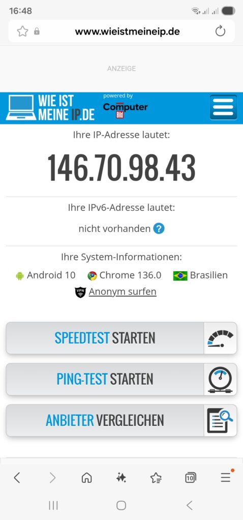
Once we have started the dnsmasq service (systemctl start dnsmasq.service) from the previous chapter and set up the routing policy correctly, we should be able to connect with a smartphone or a notebook to our new WiFi network 192.168.4.0/24 and do first tests like shown here:

Relocating the TV Set to DE, PT, BR
As a means of convenience, we want to set up a small web page that can be accessed on our smartphone so that we can “re-locate” the TV set between the countries Germany, Portugal, and Brazil. This simple “no frills” page will serve our purpose:
relocate.php:
<!DOCTYPE HTML PUBLIC "-//W3C//DTD HTML 4.0 Transitional//EN">
<html>
<head>
  <title>TV Geo-Relocation</title>
  <style type="text/css">
    a:link { text-decoration:underline; font-weight:normal; color:#0000FF; }
    a:visited { text-decoration:underline; font-weight:normal; color:#800080; }
    a:hover { text-decoration:underline; font-weight:normal; color:#909090; }
    a:active { text-decoration:blink; font-weight:normal; color:#008080; }
    h1 { font-family:Arial,Helvetica,sans-serif; font-size:100%; color:maroon; text-indent:0.0cm; }
    hr { text-indent:0.0cm; height:3px; width:100%; text-align:left; }
    p { font-family:Arial,Helvetica,sans-serif; font-size:80%; color: black; text-indent:0.0cm; }
    body { font-family: Arial, sans-serif; background-color:#FFFFD8; max-width: 600px; margin: 50px auto; padding: 20px; }
    .flag { width: 24px; height: 16px; vertical-align: middle; margin-right: 10px; }
    .radio-group { margin: 20px 0; }
    input[type="radio"] { margin-right: 5px; }
    button { padding: 10px 20px; margin: 10px; background: #007cba; color: white; border: none; cursor: pointer; }
  </style>
  <meta name="viewport" content="width=device-width, initial-scale=1.0">
  <meta http-equiv="content-language" content="de">
  <meta http-equiv="cache control" content="no-cache">
  <meta http-equiv="pragma" content="no-cache">
  <meta name="author" content="Gabriel Rüeck">
  <meta name="date" content="2026-02-17T18:00:00+01:00">
  <meta name="robots" content="noindex">
</head>

<body bgcolor="seashell">
  <?php
    // Setze die neue Markierung für Pakete aus 192.168.3.0/24
    if ($_SERVER['REQUEST_METHOD'] === 'POST') {
      $fwmark = $_POST['fwmark'] ?? '';
      if (in_array($fwmark, ['0','1','2'], true)) {
        shell_exec('sudo /srv/www/htdocs/tv/write_status.sh ' . escapeshellarg($fwmark));
      }
    }

    // Hole aktuelle Markierung für Pakete aus 192.168.3.0/24
    $current_mark = trim(shell_exec('sudo /srv/www/htdocs/tv/read_status.sh'));
  ?>
  <h1>TV Geo-Relocation</h1>

  <form method="POST">
    <div class="radio-group">
      <label>
        <input type="radio" name="fwmark" value="0" <?= $current_mark === '0x0' ? 'checked' : '' ?>>
        <img src="https://flagcdn.com/24x18/de.png" srcset="https://flagcdn.com/48x36/de.png 2x" class="flag" alt="🇩🇪"> Deutschland (0x0)
      </label><br><br>

      <label>
        <input type="radio" name="fwmark" value="1" <?= $current_mark === '0x1' ? 'checked' : '' ?>>
        <img src="https://flagcdn.com/24x18/pt.png" srcset="https://flagcdn.com/48x36/pt.png 2x" class="flag" alt="🇵🇹"> Portugal (0x1)
      </label><br><br>

      <label>
        <input type="radio" name="fwmark" value="2" <?= $current_mark === '0x2' ? 'checked' : '' ?>>
        <img src="https://flagcdn.com/24x18/br.png" srcset="https://flagcdn.com/48x36/br.png 2x" class="flag" alt="🇧🇷"> Brasilien (0x2)
      </label>
    </div>

    <button type="submit">Anwenden</button>
    <button type="button" onclick="location.reload()">Neu laden</button>

    <p>Flags with courtesy from <a href="https://flagpedia.net" target="_blank">flagpedia.net</a>.</p>
  </form>

</body>
</html>
This PHP page needs to be put in a suitable directory, and you need to have web server up and running, of course (not described in this article). In my case, the file is located in /srv/www/htdocs/tv/relocate.php. In the header of the PHP file, you can see the line:
<meta name="viewport" content="width=device-width, initial-scale=1.0">This line adapts the width of the page when being called on a smartphone so that it appears with a reasonable scaling on the smartphone screen. Furthermore, as you can see, this web page calls two shell scripts, and those are:
read_status.sh
#! /bin/bash
#
# This script will be executed as root by the PHP scipt relocate.php
#
# Gabriel Rüeck 15.02.2026
#

/usr/sbin/iptables -t mangle --line-numbers -L PREROUTING -n -v | fgrep "eth0" | sed -r 's/^.*MARK (set|and) (0x[[:xdigit:]]+)/\2/'
write_status.sh
#! /bin/bash
#
# This script will be executed as root by the PHP scipt relocate.php
#
# Gabriel Rüeck 15.02.2026
#

LINE_NUMBER=$(/usr/sbin/iptables -t mangle --line-numbers -L PREROUTING -n -v | fgrep "eth0" | sed 's/^\([[:digit:]]\+\) \+.*/\1/')
MARK=${1}
/usr/sbin/iptables -t mangle -R PREROUTING ${LINE_NUMBER} -i eth0 -s 192.168.3.0/24 -j MARK --set-mark ${MARK}
read_status.sh reads the corresponding routing entry from the mangle table [6], and this information enables the page relocate.php to display the correct country to which the traffic of the TV set if channeled when relocate.php is called initially. write_status.sh is used to modify the correct entry in the mangle table and channel the traffic to the country select on the PHP page. Both read_status.sh as well as write_status.sh need to be executed as root, and therefore, they need to be listed in the sudoers file structure. [7], [8] explain the correct proceeding. In our case, the file /etc/sudoers.d/wwwrun has been set up with the access rights 0440, and this file should have the content:
wwwrun ALL=(root) NOPASSWD: /srv/www/htdocs/tv/read_status.sh
wwwrun ALL=(root) NOPASSWD: /srv/www/htdocs/tv/write_status.sh
Of course, we do not want arbitrary internet users to change the geo-location of the TV set, and therefore, the access to the PHP page relocate.php must be restricted. An easy, but not entirely secure method is to limit access to this page to the local networks. This can be done in the webserver configuration file (in my case: /etc/apache2/httpd.conf.local) where we add:
# TV Configuration
<Directory /srv/www/htdocs/tv>
  Require local
  Require ip 192.168.0.0/16 127.0.0.0/8 ::1/128 fd00:0:0::/48
</Directory>
This will restrict access to local networks. But this is entirely fool-proof against advanced hacking attacks (see [9] as an example).
The PHP page should ultimately look like this on a smartphone:

Shortcomings
During experiments with this setup, I have come across the following shortcoming:
- On my TV set, a Samsung GQ75Q80, I was able to configure a static IPv4 address. However, it seemed to me that the TV was still getting a dynamic IPv6 address from the FRITZ!Box. I suppose that if one really wants to isolate the TV set from the SoHo network, it would be necessary to use a separate physical network. Luckily, this did not impact the possibility to watch TV with the Portuguese TV app.
Conclusion
With Policy Routing and commercial VPN connections, it is possible to create additional networks in a SoHo environment that will allow client devices to behave as if they were in another country. Basically, you could also achieve that with a VPN connection on the device (smartphone, etc.) itself; however, you then might have access to other services in your SoHo network (printer, etc.). And in the case of a TV set, I am not even sure if there are models that can build up VPN connections themselves. However, the setup described here also shows that it is not trivial as several services need to be configured and act together in a meaningful way.
Sources
- [1] = Setting up Client VPNs, Policy Routing
- [2] = Setting up Dual Stack VPNs
- [3] = iptables – Port forwarding over OpenVpn
- [4] = Routing for multiple uplinks/providers
- [5] = Two Default Gateways on One System
- [6] = Netfilter
- [7] = Classic SysAdmin: Configuring the Linux Sudoers File
- [8] = How To Edit the Sudoers File Safely
- [9] = Forcepoint Research Report: Attacking the internal network from the public Internet using a browser as a proxy
Getting around Carrier-grade NAT
Executive Summary
This blog post explains how a small internet-based shared server (“vServer”, “VPS”) can be used to tunnel connections from the internet back to a SoHo-based router that does not have a publicly routable IPv4 internet address, maybe because the internet service provider (ISP) uses Carrier-grade NAT (CG-NAT) and only offers “real” IPv4 addresses at cost. As internet-based shared servers can be rented for small fees, the approach described below is a viable concept to overcome the limitations of CG-NAT connections which might only allow outgoing connections for IPv4 or even for both IPv4 and IPv6. This concept can even be used if the SoHo server is connected via the mobile network to the internet-based shared server.
Background
The implementation proved useful for me when I switched from my DSL ISP who happily had provided me with “real” (routable) IPv4 and IPv6 addresses to a new fiber-optics ISP that provides IPv6, but that uses CG-NAT on IPv4 so that no incoming IPv4 connections are possible from the internet. As I feared that my server at home would only be accessible from the internet via IPv6, I had to develop this counterstrategy.
Preconditions
In order to use the approach described here, you should:
- … have access to a Linux machine which is already properly configured for dual stack on its principal network interface (e.g., eth0)
- … additionally have access to a cloud-based Linux server which is already properly configured for dual stack on its principal network interface
- … have access to a DNS resolver where you can enter an IPv4 and an IPv6 addresses for your SoHo server so that your domain resolves properly
- … have the package openvpn installed on both machines (preferably from a repository of your Linux distribution)
- … know how to create client and server certificates for openvpn [1]
- … have knowledge of routing concepts, networks, some understanding of shell scripts and configuration files
- … know related system commands like sysctl
- … familiarize yourself with [2], [3], [4], [5]
Description and Usage
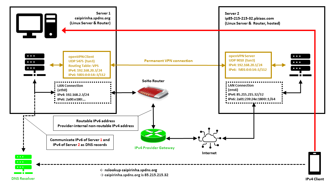
In this setup, we have a full-blown SoHo server (Server 1) which is hosting numerous services that we want to offer to the world. However, while the provider allocates an IPv6 /64 subnet, he does not offer an IPv4 address that would be reachable from the internet. Rather than that, he employs Carrier-grade NAT (CG-NAT) for IPv4. This is a typical setup for fiber-optics or cable providers or for mobile network providers. In some countries (which came late to the internet), IPv4 addresses are scarce in general, and so you might experience CG-NAT for all private internet connections.
This is where Server 2 comes into play. Server 2 is a hosted shared server, it just needs a good internet connection and a fixed IPv4 address, but it does not need a lot of computational power. It will only be used to forward traffic to Server 1. In my case, I rented a small “VPS” server from Ionos as I personally found their offer compelling [6], but there are alternatives. My VPS has a dual-stack and a fixed IPv4 address and a fixed IPv6 /64 subnet allocated. The IPv4 address of the VPS is 85.215.215.32, and we will use this IPv4 address as entry address for our SoHo server (Server 1) caipirinha.spdns.org.
A new Routing Table
We want to separate the traffic that we receive and send out in return via the VPN network (192.168.20.0/24) from the regular traffic that enters and leaves the server via the network 192.168.2.0/24. Therefore, we set up a new routing table as described in [7] and name it “VPS”. In order to access it via its name, we modify /etc/iproute2/rt_tables:
#
# reserved values
#
255 local
254 main
253 default
0 unspec
#
# local
#
#1  inr.ruhep

...
201 VPS
...
Setting up a permanent VPN
First, we need to set up a permanent VPN connection from Server 1 to Server 2. Server 1 will be the VPN client, and Server 2 will be the VPN server. I chose this direction because in that approach, Server 1 may even be connected to the internet via a mobile only connection CG-NAT both on IPv4 and IPv6. In my approach, I use the network 192.168.20.0/24 for the VPN connection; Server 1 gets the address 192.168.20.3 and Server 2 gets the address 192.168.20.1.
Server 2: The VPN Server
On Server 2, we set up a VPN server listening on port 9010 (UDP), using dev tun3. The configuration file is shown below. In my case, Server 2 is an Ubuntu-based server, and so it is recommended to adjust the settings in the configuration file /etc/default/openvpn which governs the behavior of openvpn connections on Ubuntu. I modified this configuration file so that only one openvpn service is started. This is done via the configuration option
AUTOSTART="server-9010"For the configuration of the server side, I meanwhile include the CA certificate, the server certificate and the private key in one configuration file. I find that more convenient, but it certainly may have disadvantages, The key message is that it is possible to do so. My own certificates and private keys have been substituted by “…” here, of course.
# Konfigurationsdatei für den openVPN-Server auf IONOS VPS (UDP:9010)

client-config-dir     /etc/openvpn/server/conf-9010
crl-verify            /etc/openvpn/server/crl.pem
dev                   tun3
dh                    /etc/openvpn/server/dh.pem
hand-window           90
ifconfig              192.168.20.1  255.255.255.0
ifconfig-pool         192.168.20.2  192.168.20.254  255.255.255.0
ifconfig-ipv6         fd01:0:0:14::1 2a01:239:24e:1800::1
ifconfig-ipv6-pool    fd01:0:0:14::2/112
ifconfig-pool-persist /etc/openvpn/server/ip-pool-9010.txt
keepalive             20 80
log                   /var/log/openvpn/server-9010.log
mode                  server
persist-key
persist-tun
port                  9010
proto                 udp6
reneg-sec             86400
script-security       2
status                /var/run/openvpn/status-9010
tls-server
topology              subnet
verb                  1
writepid              /var/run/openvpn/server-9010.pid

# Topologie des VPN und Default-Gateway
push "topology subnet"
push "tun-ipv6"

<ca>
-----BEGIN CERTIFICATE-----
...
-----END CERTIFICATE-----
</ca>

<cert>
-----BEGIN CERTIFICATE-----
...
-----END CERTIFICATE-----
</cert>

<key>
-----BEGIN PRIVATE KEY-----
...
-----END PRIVATE KEY-----
</key>
We also must take care that our client always gets the IP address 192.168.20.3 as we originally envisioned. This is done with the client-specific configuration file /etc/openvpn/server/conf-9010/caipirinha_client:
# Spezielle Konfigurationsdatei für den Server caipirinha.spdns.org als Client
#

ifconfig-push      192.168.20.3 255.255.255.0
ifconfig-ipv6-push fd01:0:0:14::3/111 fd01:0:0:14::1
The client-specific configuration file additionally also allocates the static IPv6 address fd01:0:0:14::3 to our client. Finally, the service can then be started with:
systemctl start openvpn@server-9010.serviceServer 1: The VPN Client
On Server 1, we set up a VPN client using dev tun3. The local port shall always be 5475 (arbitrarily chosen but fixed so that we can track the connection easily if necessary). Server 2 is addressed via its public IPv6 address (2a01:239:24e:1800::1), but we could also have used its public IPv4 address (85.215.215.32). I chose the IPv6 address because the IPv4 connection would run via the provider gateway, and that might slow down the connection or make it less reliable.
# Konfigurationsdatei für den openVPN-Client auf caipirinha.spdns.org zum IONOS-Server

client
dev              tun3
explicit-exit-notify
hand-window      90
keepalive        10 60
log              /var/log/openvpn_ionos_vpn.log
lport            5475
persist-key
persist-tun
proto            udp
remote           2a01:239:24e:1800::1 9010
remote-cert-tls  server
remote-random
reneg-sec        86400
route-nopull
script-security  2
status           /var/run/openvpn/status_ionos_vpn
up               /etc/openvpn/start_piavpn.sh
verb             1

<ca>
-----BEGIN CERTIFICATE-----
...
-----END CERTIFICATE-----
</ca>

<cert>
-----BEGIN CERTIFICATE-----
...
-----END CERTIFICATE-----
</cert>

<key>
-----BEGIN PRIVATE KEY-----
...
-----END PRIVATE KEY-----
</key>
One peculiarity is the referenced script /etc/openvpn/start_piavpn.sh. At the start of the VPN connection, this script populates the routing table VPS:
#!/bin/bash
#
# This script requires the tool "ipcalc" which needs to be installed on the target system.

# Set the correct PATH environment
PATH='/sbin:/usr/sbin:/bin:/usr/bin'

VPN_DEV=$1
VPN_SRC=$4
VPN_MSK=$5

VPN_GW=$(ipcalc ${VPN_SRC}/${VPN_MSK} | sed -n 's/^HostMin:\s*\([0-9]\{1,3\}\.[0-9]\{1,3\}\.[0-9]\{1,3\}\.[0-9]\{1,3\}\).*/\1/p')
VPN_NET=$(ipcalc ${VPN_SRC}/${VPN_MSK} | sed -n 's/^Network:\s*\([0-9]\{1,3\}\.[0-9]\{1,3\}\.[0-9]\{1,3\}\.[0-9]\{1,3\}\/[0-9]\{1,2\}\).*/\1/p')

case "${VPN_DEV}" in
  "tun0") ROUTING_TABLE='Portugal';;
  "tun1") ROUTING_TABLE='Brasilien';;
  "tun2") ROUTING_TABLE='Singapur';;
  "tun3") ROUTING_TABLE='VPS';;
  "tun8") ROUTING_TABLE='China';;
esac

...

ip route add ${VPN_NET} dev ${VPN_DEV} proto static scope link src ${VPN_SRC} table ${ROUTING_TABLE}
ip route replace default dev ${VPN_DEV} via ${VPN_GW} table ${ROUTING_TABLE}
When the VPN connection is stopped, then the VPN network and the default route are automatically deleted from the routing table VPS as the VPN network collapses. While the VPN connection is up, we can view the routing table VPS with:
caipirinha:~ # ip route list table VPS
default via 192.168.20.1 dev tun3
192.168.20.0/24 dev tun3 proto static scope link src 192.168.20.3
Finally, the client can be started with:
systemctl start openvpn@client_ionos_vps.serviceOf course, the actual name after “openvpn@” in this command depends on how you named the respective client configuration file.
Channeling the Traffic
Now, we must make sure that traffic that is received by Server 2 and that shall be forwarded to Server 1 is channeled in an appropriate way through the VPN connection. We need to execute some commands on both servers. [3], [4] explain how that can be achieved.
Server 2: Forward the traffic
We need to enable IPv4 routing and simply forward connections to those ports where we offer our service on Server 1. This is done by:
sysctl -w net.ipv4.ip_forward=1

iptables -t nat -A PREROUTING -p tcp -m multiport --dports 20,21,25,80,443,465,587,873,993,3000,4078:4088,8009,8080:8082 -j DNAT --to-destination 192.168.20.3
iptables -t nat -A PREROUTING -p udp -m multiport --dports 1194,2372:2380,4396,44576 -j DNAT --to-destination 192.168.20.3
We need two iptables commands, one for TCP connections and one for UDP connections. Both are located in the PREROUTING chain. As we can see, we can combine various ports and even port ranges that shall be forwarded in one command, that is very handy. Of course, you should only forward the ports that correspond to services on Server 1 that you want to offer to the world. It is also possible to offer the services on different ports on Server 2, so that http is listening on port 81 TCP rather than on 80 TCP although in my opinion, that does not make much sense.
Let us assume that a client initiates a connection to Server 2 on port 80 (http). The first iptables command changes the destination IP from the IP address of Server 2 (85.215.215.32) to the IP address 192.168.20.3 which is the VPN client on Server 1. As we have enabled routing on Server 2, the packet is routed from ens6 to tun3 and leaves Server 2 via the VPN connection to Server 1.
Server 1: Accept the traffic in Routing Table VPS
Server 1 receives the traffic and needs to channel it via routing table VPS. This is done with the command:
ip rule add from 192.168.20.3 priority 1000 table VPSThe beauty of this command is that the outgoing traffic will also use table VPS and therefore leave Server 1 not via the default interface eth0 to the SoHo router, but via tun3 back to Server 2 (see [4], [8]). We can identify the traffic that we receive from Server 2 at Server 1 with the conntrack command:
caipirinha:~ # conntrack -L | fgrep "192.168.20"
tcp      6 117 TIME_WAIT src=109.250.125.241 dst=192.168.20.3 sport=55370 dport=80 src=192.168.20.3 dst=109.250.125.241 sport=80 dport=55370 [ASSURED] mark=0 use=1
tcp      6 117 TIME_WAIT src=109.250.125.241 dst=192.168.20.3 sport=55366 dport=80 src=192.168.20.3 dst=109.250.125.241 sport=80 dport=55366 [ASSURED] mark=0 use=1
tcp      6 117 TIME_WAIT src=109.250.125.241 dst=192.168.20.3 sport=55368 dport=80 src=192.168.20.3 dst=109.250.125.241 sport=80 dport=55368 [ASSURED] mark=0 use=1
In that case, we have observed a https request (dport=80) from the source IP 109.250.125.241 which has been tunneled via our VPN from Server 2 to Server 1. The client (represented by a mobile phone in the image above) has basically access Server 2 along the red arrow drawn in the image. The benefit of the concept described here is also that the source address (here: 109.250.125.241) is not concealed and therefore, filtering can be done on Server 1 with iptables as if Server 1 was accessed directly. Furthermore, the correct client IP address is in the respective log files.
Other approaches which use SNAT on Server 2 would conceal the source address of the client and therefore, such filtering would have to occur on Server 2 already. The logs on Server 1 however would contain 192.168.20.1 as sole source address for all incoming connections which is why such an approach is not suitable.
Updating the DNS Server
Now we should spend some thoughts on the domain name resolution of Server 1. In my case, I already had a script that communicated any change of the IP address of Server 1 provoked by the ISP almost on a daily basis to a Dynamic DNS (DDNS) provider which so far has done the name resolution for clients that want to access Server 1. I use my own script, but most DDNS providers also offer pre-written scripts for certain architectures or routers.
In our concept though, we must communicate the IPv6 address of Server 1 and the IPv4 address of Server 2 to our DDNS service. As Server 2 has a static IPv4 address, adapting any script should be easy. Alternatively, one could limit the script to only update the IPv6 address of Server 1 and enter the static IPv4 address via the web-based user interface of the DDNS hoster.
Conclusion
This blog post shows how we can channel back traffic via a small internet-based server to a powerful server that is connected via CG-NAT and that may therefore not be accessible directly from the internet. With the approach described here, Server 1 can even be located in a mobile network or inside a firewalled environment as long as the firewall permits outgoing openvpn connections.
Sources
- [1] = Setting up your own Certificate Authority (CA) and generating certificates and keys for an OpenVPN server and multiple clients
- [2] = Setting up Dual Stack VPNs
- [3] = iptables – Port forwarding over OpenVpn
- [4] = Routing for multiple uplinks/providers
- [5] = Predictable Network Interface Names
- [6] = vServer Günstig Mieten » VPS ab 1€ / M.
- [7] = Setting up Client VPNs, Policy Routing
- [8] = Two Default Gateways on One System
Setting up Client VPNs, Policy Routing
Executive Summary
This blog post is the continuation my previous blog post Setting up Dual Stack VPNs and explains how I use client VPNs together with simple Policy Routing on my Linux server in order to relegate outgoing connections to various network interfaces and, ultimately, to different countries. The examples use IPv4 only.
Background
The approach was originally developed back in 2011…2014 when I lived in China and maintained several outgoing VPN connections from my Linux server to end points “in the West” so that I could circumvent internet censorship in China [8]. With the VPN service described Setting up Dual Stack VPNs, it was then possible for me to be in town and to connect the smartphone to my Linux server (in the same town). From there, the connections to sites blocked in China would run over the client VPNs of the Linux server so that I could use Google Maps on my smartphone, for example (which at that time had already been blocked in China).
Preconditions
Routing in Linux follows some very clever approaches which can be combined in mighty ways. Those readers who want to understand all of the underlying theory, are encouraged to study the (older) documents [1], [2], [3], even if parts of the content might not be relevant any more. Those readers who just want to follow and replicate the approach in this blog, should at least study the documents [4], [5], [6].
Apart from that, in order to replicate the approach described here, you should:
- … fulfil all preconditions listed in the blog post Setting up Dual Stack VPNs
- … have running the setup similar to the one described in the blog post Setting up Dual Stack VPNs
- … have access to a commercial VPN provider allowing you to run several client connections on the same machine
- … have at least read the documents [4], [5], [6]
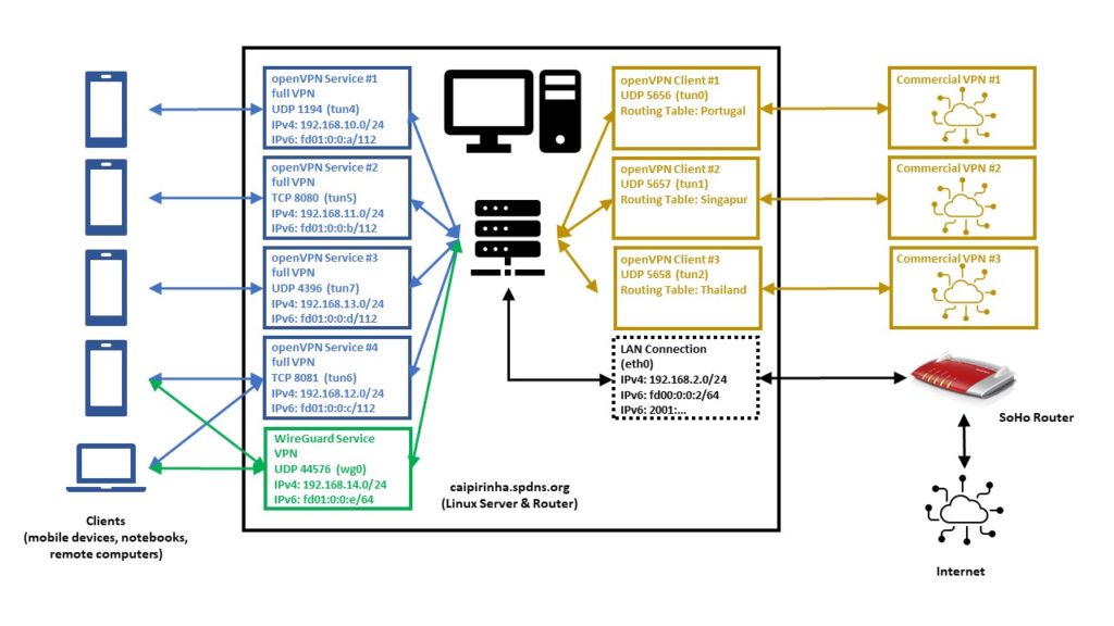
Description and Usage
The graph below shows the setup on my machine caipirinha.spdns.org with. The 5 VPN services (blue, green color) were already described in blog post Setting up Dual Stack VPNs. Now, we have a close look at the 3 VPN clients which use a commercial VPN service (ocker color) in order to connect to VPN end points in 3 different countries (Portugal, Singapore, Thailand).
Enabling Routing
Routing needs to be enabled on the Linux server. I personally also decided to switch off the privacy extensions on the Linux server, but that is a personal matter of taste:
# Enable "loose" reverse path filtering and prohibit icmp redirects
sysctl -w net.ipv4.conf.all.rp_filter=2
sysctl -w net.ipv4.conf.all.send_redirects=0
sysctl -w net.ipv4.conf.eth0.send_redirects=0
sysctl -w net.ipv4.icmp_errors_use_inbound_ifaddr=1

# Enable IPv6 routing, but keep SLAAC for eth0
sysctl -w net.ipv6.conf.eth0.accept_ra=2
sysctl -w net.ipv6.conf.all.forwarding=1

# Switch off the privacy extensions
sysctl -w net.ipv6.conf.eth0.use_tempaddr=0
Routing Tables
We now must have a closer look at the concept of the routing table. A routing tables basically lists routes to particular network destinations. An example is the routing table main on my Linux server. It reads:
caipirinha:~ # ip route list table main
default via 192.168.2.1 dev eth0 proto dhcp
192.168.2.0/24 dev eth0 proto kernel scope link src 192.168.2.3
192.168.10.0/24 dev tun4 proto kernel scope link src 192.168.10.1
192.168.11.0/24 dev tun5 proto kernel scope link src 192.168.11.1
192.168.12.0/24 dev tun6 proto kernel scope link src 192.168.12.1
192.168.13.0/24 dev tun7 proto kernel scope link src 192.168.13.1
192.168.14.0/24 dev wg0 proto kernel scope link src 192.168.14.1
This table has 7 entries, and they have this meaning:
- (“default via…”) Connections to IP addresses that do not have a corresponding entry in the routing table shall be forwarded via the interface eth0 and to the router IP address 192.168.2.1 (an AVM Fritz! Box).
- Connections to the network 192.168.2.0/24 shall be forwarded via the interface eth0 using the source IP address 192.168.2.3 (the Linux server itself).
- Connections to the network 192.168.10.0/24 shall be forwarded via the interface tun4 using the source IP address 192.168.10.1 (the Linux server itself). This network belongs to one of the 5 VPN services on my Linux server.
- Connections to the network 192.168.11.0/24 shall be forwarded via the interface tun5 using the source IP address 192.168.11.1 (the Linux server itself). This network belongs to one of the 5 VPN services on my Linux server.
- Connections to the network 192.168.12.0/24 shall be forwarded via the interface tun6 using the source IP address 192.168.12.1 (the Linux server itself). This network belongs to one of the 5 VPN services on my Linux server.
- Connections to the network 192.168.13.0/24 shall be forwarded via the interface tun7 using the source IP address 192.168.13.1 (the Linux server itself). This network belongs to one of the 5 VPN services on my Linux server.
- Connections to the network 192.168.14.0/24 shall be forwarded via the interface wg0 using the source IP address 192.168.14.1 (the Linux server itself). This network belongs to one of the 5 VPN services on my Linux server.
Usually, a routing table should have a default entry which sends all IP traffic that is not explicitly routed to other network interfaces to the default router of a network. Otherwise, no meaningful internet access is possible.
A Linux system can have up to 256 routing tables which are defined in /etc/iproute2/rt_tables. They can either be used by their number or by their name. On my Linux server, I have set up 3 additional routing tables, named “Portugal”, “Singapur”, “Thailand”. You can see in the file /etc/iproute2/rt_tables that besides the table main, the tables local, default, and unspec do already exist, but they are not of interest for our purposes.
#
# reserved values
#
255 local
254 main
253 default
0 unspec
#
# local
#
#1  inr.ruhep

240 Portugal
241 Singapur
242 Thailand
Right now (before we set up the client VPNs), all 3 routing tables look the same as shown here:
caipirinha:~ # ip route list table Portugal
192.168.2.0/24 dev eth0 proto kernel scope link src 192.168.2.3
192.168.10.0/24 via 192.168.10.1 dev tun4
192.168.11.0/24 via 192.168.11.1 dev tun5
192.168.12.0/24 via 192.168.12.1 dev tun6
192.168.13.0/24 via 192.168.13.1 dev tun7
192.168.14.0/24 via 192.168.14.1 dev wg0
caipirinha:~ # ip route list table Singapur
192.168.2.0/24 dev eth0 proto kernel scope link src 192.168.2.3
192.168.10.0/24 via 192.168.10.1 dev tun4
192.168.11.0/24 via 192.168.11.1 dev tun5
192.168.12.0/24 via 192.168.12.1 dev tun6
192.168.13.0/24 via 192.168.13.1 dev tun7
192.168.14.0/24 via 192.168.14.1 dev wg0
caipirinha:~ # ip route list table Thailand
192.168.2.0/24 dev eth0 proto kernel scope link src 192.168.2.3
192.168.10.0/24 via 192.168.10.1 dev tun4
192.168.11.0/24 via 192.168.11.1 dev tun5
192.168.12.0/24 via 192.168.12.1 dev tun6
192.168.13.0/24 via 192.168.13.1 dev tun7
192.168.14.0/24 via 192.168.14.1 dev wg0
The content of routing tables can be listed with the command ip route list table ${tablename}, and ${tablename} needs to exist in /etc/iproute2/rt_tables. It is important to notice that so far, none of these 3 routing tables have a default route. They only contain the home network and the networks of the 5 VPN services. Right now, these tables are not yet useful. In case you wonder how it comes that these 3 routing tables are populated with their entries. That needs to done either manually or by a script (see next chapter).
OpenVPN Server Configuration (Update)
Now that we have 3 additional routing tables, we must ensure that the networks of our 5 VPN services are also inserted in these 3 routing tables. Therefore, we modify the configuration files described in the blog post Setting up Dual Stack VPNs so that a script runs when the VPN service is started. In the configuration files for the openvpn configuration, we insert the statement:
up /etc/openvpn/start_vpn.shIn the configuration files for the WireGuard configuration, we insert the statement:
PostUp = /etc/openvpn/start_vpn.sh %i - - 192.168.14.1The effect of these statements is that the script /etc/openvpn/start_vpn.sh is executed when the VPN service has been set up. If no arguments are specified, openvpn hands over 5 arguments to the scripts (see [9], section “–up cmd”). In the WireGuard configuration, we have to explicitly specify the arguments, the “%i” means the interface (see [10], “PostUp”). In my case, “%i” hence stands for wg0.
The script /etc/openvpn/start_vpn.sh was originally developed for the openvpn configuration and therefore intakes all the default arguments that openvpn transmits, although only the first and the fourth argument are used. Therefore, in the WireGuard configuration, there are two “-” inserted as bogus arguments. That is surely something that can be solved more elegantly.
What does this script do? It essentially writes the same entry that is done automatically in the routing table main to the 3 additional routing tables Portugal, Singapur, and Thailand. It assumes that VPN services have a /24 network (true in my own case, not necessarily for other setups).
#!/bin/bash
#
# This script sets the VPN parameters in the routing tables "Portugal", "Singapur" and "Thailand" once the server has been started successfully.

# Set the correct PATH environment
PATH='/sbin:/usr/sbin:/bin:/usr/bin'

VPN_DEV="${1}"
VPN_SRC="${4}"
VPN_NET=$(echo "${VPN_SRC}" | cut -d . -f 1-3)".0/24"

for TABLE in Portugal Singapur Thailand; do
    ip route add ${VPN_NET} dev ${VPN_DEV} via ${VPN_SRC} table ${TABLE}
done
For our experiments, we now also need to allocate 3 dedicated IP addresses to 3 devices in one of the VPN services on the Linux server so that the devices always get the same IP address by the VPN service when they connect (pseudo-static IP configuration). As described in the blog post Setting up Dual Stack VPNs, section “Dedicated Configurations”, we can achieve this by creating 3 files with the common names of the devices (gabriel-SM-G991B, gabriel-SM-N960F, gabriel-SM-T580) that were used to create their certificates. I did that for the UDP-based VPN, full tunneling openvpn, and the 3 configuration files are listed here:
caipirinha:~ # cat /etc/openvpn/conf-1194/gabriel-SM-G991B
# Spezielle Konfigurationsdatei für Gabriels Galaxy S20 (gabriel-SM-G991B)
#

ifconfig-push      192.168.10.250  255.255.255.0
ifconfig-ipv6-push fd01:0:0:a:0:0:1:fa/111 fd01:0:0:a::1
caipirinha:~ # cat /etc/openvpn/conf-1194/gabriel-SM-N960F
# Spezielle Konfigurationsdatei für Gabriels Galaxy Note 9 (gabriel-SM-N960F)
#

ifconfig-push      192.168.10.251  255.255.255.0
ifconfig-ipv6-push fd01:0:0:a:0:0:1:fb/111 fd01:0:0:a::1
caipirinha:~ # cat /etc/openvpn/conf-1194/gabriel-SM-T580
# Spezielle Konfigurationsdatei für Gabriels Galaxy Tablet A (gabriel-SM-T580)
#

ifconfig-push      192.168.10.252  255.255.255.0
ifconfig-ipv6-push fd01:0:0:a:0:0:1:fc/111 fd01:0:0:a::1
One can easily identify the respective IPv4 and IPv6 addresses which shall be allocated to the 3 named devices:
- gabriel-SM-G991B shall get the IPv4 192.168.10.250 and the IPv6 fd01:0:0:a:0:0:1:fa.
- gabriel-SM-N960F shall get the IPv4 192.168.10.251 and the IPv6 fd01:0:0:a:0:0:1:fb.
- gabriel-SM-T580 shall get the IPv4 192.168.10.252 and the IPv6 fd01:0:0:a:0:0:1:fc.
Let us not forget that this is the configuration for only one out of the 5 VPN services. If the devices connect to a VPN service different from the UDP-based VPN, full tunneling openvpn, then, these configurations do not have any effect.
OpenVPN Client Configuration
For the experiments below, we will set up 3 client VPN connections to different countries. As I do not have infrastructure outside of Germany, I use a commercial VPN provider, in my case this is PureVPN™ (as I once got an affordable 5-years subscription). Choosing a suitable VPN provider is not easy, and I strongly recommend to research test reports and forums which deal with the configuration on Linux before you choose any subscription to a commercial VPN provider. In my case, the provider (PureVPN™) offers openvpn Linux configuration as a download. I just had to make some modifications as otherwise, the VPN wants to be the default connection for all internet traffic; this is not what we want when we do our own policy routing. I chose the TCP configuration as the UDP configuration, which is normally preferred, did not run in a stable fashion at the time of writing this article. The client configuration files also contain the ca, the certificate, and the key file at the end (not shown here).
TCP-based split VPN to Portugal
# Konfigurationsdatei für den openVPN-Client auf CAIPIRINHA zur Verbindung nach PureVPN (Portugal)

auth-user-pass       /etc/openvpn/purevpn.login
auth-nocache
auth-retry           nointeract
client
comp-lzo
dev                  tun0
ifconfig-nowarn
key-direction        1
log                  /var/log/openvpn_PT.log
lport                5456
mute                 20
proto                tcp
persist-key
persist-tun
remote               pt2-auto-tcp.ptoserver.com 80
remote-cert-tls      server
route-nopull
script-security      2
status               /var/run/openvpn/status_PT
up                   /etc/openvpn/start_purevpn.sh
down                 /etc/openvpn/stop_purevpn.sh
verb                 3

<ca>
-----BEGIN CERTIFICATE-----
MIIE6DCCA9CgAwIBAgIJAMjXFoeo5uSlMA0GCSqGSIb3DQEBCwUAMIGoMQswCQYD
...
4ZjTr9nMn6WdAHU2
-----END CERTIFICATE-----
</ca>
<cert>
-----BEGIN CERTIFICATE-----
MIIEnzCCA4egAwIBAgIBAzANBgkqhkiG9w0BAQsFADCBqDELMAkGA1UEBhMCSEsx
...
21oww875KisnYdWjHB1FiI+VzQ1/gyoDsL5kPTJVuu2CoG8=
-----END CERTIFICATE-----
</cert>
<key>
-----BEGIN PRIVATE KEY-----
MIICdgIBADANBgkqhkiG9w0BAQEFAASCAmAwggJcAgEAAoGBAMbJ8p+L+scQz57g
...
d7q7xhec5WHlng==
-----END PRIVATE KEY-----
</key>
<tls-auth>
#
# 2048 bit OpenVPN static key
#
-----BEGIN OpenVPN Static key V1-----
e30af995f56d07426d9ba1f824730521
...
dd94498b4d7133d3729dd214a16b27fb
-----END OpenVPN Static key V1-----
</tls-auth>
TCP-based split VPN to Singapore
# Konfigurationsdatei für den openVPN-Client auf CAIPIRINHA zur Verbindung nach PureVPN (Singapur)

auth-user-pass       /etc/openvpn/purevpn.login
auth-nocache
auth-retry           nointeract
client
comp-lzo
dev                  tun1
ifconfig-nowarn
key-direction        1
log                  /var/log/openvpn_SG.log
lport                5457
mute                 20
proto                tcp
persist-key
persist-tun
remote               sg2-auto-tcp.ptoserver.com 80
remote-cert-tls      server
route-nopull
script-security      2
status               /var/run/openvpn/status_SG
up                   /etc/openvpn/start_purevpn.sh
down                 /etc/openvpn/stop_purevpn.sh
verb                 3
...
TCP-based split VPN to Thailand
# Konfigurationsdatei für den openVPN-Client auf CAIPIRINHA zur Verbindung nach PureVPN (Thailand)

auth-user-pass       /etc/openvpn/purevpn.login
auth-nocache
auth-retry           nointeract
client
comp-lzo
dev                  tun2
ifconfig-nowarn
key-direction        1
log                  /var/log/openvpn_TH.log
lport                5458
mute                 20
proto                tcp
persist-key
persist-tun
remote               th2-auto-tcp.ptoserver.com 80
remote-cert-tls      server
route-nopull
script-security      2
status               /var/run/openvpn/status_TH
up                   /etc/openvpn/start_purevpn.sh
down                 /etc/openvpn/stop_purevpn.sh
verb                 3
...
I stored these configurations in the files:
- /etc/openvpn/client_PT.conf
- /etc/openvpn/client_SG.conf
- /etc/openvpn/client_TH.conf
Let us discuss some configuration items:
- auth-user-pass refers to the file /etc/openvpn/purevpn.login which contains the login and password for my VPN service. It is referenced here so that I do not have to enter them when I start the connection or when the connection restarts after a breakdown.
- cipher refers to an algorithm that PureVPN™ uses on their server side.
- PureVPN™ also uses compression on the VPN connection, and this is turned on by the line comp-lzo.
- As we want to do policy routing, we need to know which VPN we are dealing with. Therefore, I attribute a dedicated tun device as well as a dedicated lport (source port) to each connection.
- remote names the server and port given in the downloaded configuration files.
- route-nopull is very important as otherwise, the default route would be changed. However, for our purposes, we do not want any routes to be changed automatically, we will do that by policy routing later.
- up and down name a start and a stop script. The start script is executed after the connection has been established, and the stop script is executed when the connection is disbanded. As the scripts use various command, we need to set script-security accordingly.
- The initial configuration always takes some time, and so I have set verb to “3” in order to have more verbosity in the log file, for debugging purposes.
Let’s now look at the start script /etc/openvpn/start_purevpn.sh. This script depends on the installation of the tool library ipcalc as this library eases some computations.
#!/bin/bash
#
# This script sets the VPN parameters in the routing tables "main", "Portugal", "Singapur" and "Thailand" once the connection has been successfully established.
# This script requires the tool "ipcalc" which needs to be installed on the target system.

# Set the correct PATH environment
PATH='/sbin:/usr/sbin:/bin:/usr/bin'

VPN_DEV=$1
VPN_SRC=$4
VPN_MSK=$5

VPN_GW=$(ipcalc ${VPN_SRC}/${VPN_MSK} | sed -n 's/^HostMin:\s*\([0-9]\{1,3\}\.[0-9]\{1,3\}\.[0-9]\{1,3\}\.[0-9]\{1,3\}\).*/\1/p')
VPN_NET=$(ipcalc ${VPN_SRC}/${VPN_MSK} | sed -n 's/^Network:\s*\([0-9]\{1,3\}\.[0-9]\{1,3\}\.[0-9]\{1,3\}\.[0-9]\{1,3\}\/[0-9]\{1,2\}\).*/\1/p')

case "${VPN_DEV}" in
  "tun0") ROUTING_TABLE='Portugal';;
  "tun1") ROUTING_TABLE='Singapur';;
  "tun2") ROUTING_TABLE='Thailand';;
esac

iptables -t filter -A INPUT   -i ${VPN_DEV} -m state --state NEW,INVALID -j DROP
iptables -t filter -A FORWARD -i ${VPN_DEV} -m state --state NEW,INVALID -j DROP

ip route add ${VPN_NET} dev ${VPN_DEV} proto kernel scope link src ${VPN_SRC} table ${ROUTING_TABLE}
ip route replace default dev ${VPN_DEV} via ${VPN_GW} table ${ROUTING_TABLE}
What does this script do? It executes these steps:
- It blocks connections with the state NEW or INVALID in the filter chains INPUT and FORWARD. Later (down in this article), this shall be explained more in detail. For now, it suffices to know that we want to avoid those connections that originate from the commercial VPN network shall be blocked. We must keep in mind that by using commercial VPN connections, we make the Linux server vulnerable to connections that might come from these networks. If everything was correctly configured on the side of the VPN provider, there should never be such a connection that originates from the network because individual VPN users should not be able to “see” each other. There should only be connections that originate from our Linux server, and subsequently, we will get reply packets, of course, and have a bidirectional communication. Nevertheless, my own experience with various VPN providers has shown that there is a certain amount of unrelated stray packets that reach the Linux server, and I want to filter those out.
- It adds the client network (here, a /27 network) to the respective routing table Portugal, Singapore, or Thailand.
- It sets the default route in the respective routing table to the VPN endpoint. Ultimately, every routing table gets a default route if all 3 client VPNs are engaged. I use ip route replace rather than ip route add because ip route replace does not throw an error if there is already a default route in the routing table.
Consequently, the script /etc/openvpn/stop_purevpn.sh serves to clean up the entries in the filter table. We do not have to remove the entries in the 3 additional routing tables as they disappear automatically when the VPN connection is disbanded. This script is somewhat smaller:
#!/bin/bash
#
# This script removes some routing table entries when the connection is terminated.

# Set the correct PATH environment
PATH='/sbin:/usr/sbin:/bin:/usr/bin'

VPN_DEV=$1

iptables -t filter -D INPUT   -i ${VPN_DEV} -m state --state NEW,INVALID -j DROP
iptables -t filter -D FORWARD -i ${VPN_DEV} -m state --state NEW,INVALID -j DROP
Now, that we have all these pieces together, we start the 3 client VPNs with the commands:
systemctl start openvpn@client_PT
systemctl start openvpn@client_SG
systemctl start openvpn@client_TH
After some seconds, the 3 client VPN connections should have fully been set up, and the respective network devices tun0, tun1, tun2 should exist. Similar to what was described in the blog post Setting up Dual Stack VPNs, we must configure network address translation for the 3 client VPNs so that outgoing packets get modified in a way that they have the source IP address of the Linux server for the specific interface over which those packets shall travel. That is done with:
iptables -t nat -A POSTROUTING -o tun0 -j MASQUERADE
iptables -t nat -A POSTROUTING -o tun1 -j MASQUERADE
iptables -t nat -A POSTROUTING -o tun2 -j MASQUERADE
We use MASQUERADE in this case because the IP address of the Linux server can change at each VPN connection, and we do not know the source address beforehand. Otherwise SNAT would be the better option that consumes less CPU power.
Now, we should be able to ping a machine (in this example, Google‘s DNS) via each of the 3 client VPN connections, as shown here:
caipirinha:~ # ping -c 3 -I tun0 8.8.8.8
PING 8.8.8.8 (8.8.8.8) from 172.17.66.34 tun0: 56(84) bytes of data.
64 bytes from 8.8.8.8: icmp_seq=1 ttl=119 time=57.7 ms
64 bytes from 8.8.8.8: icmp_seq=2 ttl=119 time=54.5 ms
64 bytes from 8.8.8.8: icmp_seq=3 ttl=119 time=54.7 ms

--- 8.8.8.8 ping statistics ---
3 packets transmitted, 3 received, 0% packet loss, time 2003ms
rtt min/avg/max/mdev = 54.516/55.649/57.727/1.483 ms
caipirinha:~ # ping -c 3 -I tun1 8.8.8.8
PING 8.8.8.8 (8.8.8.8) from 10.12.42.41 tun1: 56(84) bytes of data.
64 bytes from 8.8.8.8: icmp_seq=1 ttl=58 time=249 ms
64 bytes from 8.8.8.8: icmp_seq=2 ttl=58 time=247 ms
64 bytes from 8.8.8.8: icmp_seq=3 ttl=58 time=247 ms

--- 8.8.8.8 ping statistics ---
3 packets transmitted, 3 received, 0% packet loss, time 2002ms
rtt min/avg/max/mdev = 247.120/247.972/249.111/1.015 ms
caipirinha:~ # ping -c 3 -I tun2 8.8.8.8
PING 8.8.8.8 (8.8.8.8) from 10.31.6.38 tun2: 56(84) bytes of data.
64 bytes from 8.8.8.8: icmp_seq=1 ttl=117 time=13.9 ms
64 bytes from 8.8.8.8: icmp_seq=2 ttl=117 time=14.2 ms
64 bytes from 8.8.8.8: icmp_seq=3 ttl=117 time=22.6 ms

--- 8.8.8.8 ping statistics ---
3 packets transmitted, 3 received, 0% packet loss, time 2001ms
rtt min/avg/max/mdev = 13.910/16.934/22.641/4.039 ms
caipirinha:~ # traceroute -i eth0 8.8.8.8
traceroute to 8.8.8.8 (8.8.8.8), 30 hops max, 60 byte packets
 1  Router-EZ (192.168.2.1)  3.039 ms  2.962 ms  2.927 ms
 2  fra1813aihr002.versatel.de (62.214.63.145)  15.440 ms  16.978 ms  18.866 ms
 3  62.72.71.113 (62.72.71.113)  16.116 ms  19.534 ms  19.506 ms
 4  89.246.109.249 (89.246.109.249)  24.717 ms  25.460 ms  24.659 ms
 5  72.14.204.148 (72.14.204.148)  20.530 ms  20.602 ms 89.246.109.250 (89.246.109.250)  24.573 ms
 6  * * *
 7  dns.google (8.8.8.8)  20.265 ms  16.966 ms  14.751 ms
caipirinha:~ # traceroute -i tun0 8.8.8.8
traceroute to 8.8.8.8 (8.8.8.8), 30 hops max, 60 byte packets
 1  10.96.10.33 (10.96.10.33)  50.579 ms  101.574 ms  102.216 ms
 2  91.205.230.65 (91.205.230.65)  121.175 ms  121.171 ms  151.320 ms
 3  cr1.lis1.edgoo.net (193.163.151.1)  102.156 ms  102.155 ms  102.150 ms
 4  Google.AS15169.gigapix.pt (193.136.250.20)  102.145 ms  103.099 ms  103.145 ms
 5  74.125.245.100 (74.125.245.100)  103.166 ms 74.125.245.118 (74.125.245.118)  103.156 ms 74.125.245.117 (74.125.245.117)  103.071 ms
 6  142.250.237.83 (142.250.237.83)  120.681 ms 142.250.237.29 (142.250.237.29)  149.742 ms 142.251.55.151 (142.251.55.151)  110.302 ms
 7  74.125.242.161 (74.125.242.161)  108.651 ms 108.170.253.241 (108.170.253.241)  108.594 ms 108.170.235.178 (108.170.235.178)  108.426 ms
 8  74.125.242.161 (74.125.242.161)  108.450 ms  108.429 ms 142.250.239.27 (142.250.239.27)  107.505 ms
 9  142.251.54.149 (142.251.54.149)  107.406 ms 142.251.60.115 (142.251.60.115)  108.446 ms 142.251.54.151 (142.251.54.151)  157.613 ms
10  dns.google (8.8.8.8)  107.380 ms  89.640 ms  73.506 ms
caipirinha:~ # traceroute -i tun1 8.8.8.8
traceroute to 8.8.8.8 (8.8.8.8), 30 hops max, 60 byte packets
 1  10.12.34.1 (10.12.34.1)  295.583 ms  561.820 ms  625.195 ms
 2  146.70.67.65 (146.70.67.65)  687.601 ms  793.792 ms  825.806 ms
 3  193.27.15.178 (193.27.15.178)  1130.988 ms  1198.522 ms  1260.560 ms
 4  37.120.220.218 (37.120.220.218)  1383.152 ms 37.120.220.230 (37.120.220.230)  825.525 ms 37.120.220.218 (37.120.220.218)  925.081 ms
 5  103.231.152.50 (103.231.152.50)  1061.923 ms  1061.945 ms 15169.sgw.equinix.com (27.111.228.150)  993.095 ms
 6  108.170.240.225 (108.170.240.225)  1320.654 ms 74.125.242.33 (74.125.242.33)  1164.303 ms 108.170.254.225 (108.170.254.225)  1008.590 ms
 7  74.125.251.205 (74.125.251.205)  1009.043 ms 74.125.251.207 (74.125.251.207)  993.251 ms 142.251.49.191 (142.251.49.191)  969.879 ms
 8  dns.google (8.8.8.8)  1001.502 ms  1065.558 ms  1073.731 ms
caipirinha:~ # traceroute -i tun2 8.8.8.8
traceroute to 8.8.8.8 (8.8.8.8), 30 hops max, 60 byte packets
 1  10.31.3.33 (10.31.3.33)  189.134 ms  399.914 ms  399.941 ms
 2  * * *
 3  * * *
 4  * * *
 5  198.84.50.182.static-corp.jastel.co.th (182.50.84.198)  411.679 ms  411.729 ms  411.662 ms
 6  72.14.222.138 (72.14.222.138)  433.761 ms 74.125.48.212 (74.125.48.212)  444.509 ms 72.14.223.80 (72.14.223.80)  444.554 ms
 7  108.170.250.17 (108.170.250.17)  647.768 ms * 108.170.249.225 (108.170.249.225)  439.883 ms
 8  142.250.62.59 (142.250.62.59)  635.318 ms 142.251.224.15 (142.251.224.15)  417.842 ms dns.google (8.8.8.8)  600.600 ms
A traceroute to Google‘s DNS via the 3 client VPN connections shows us the route the packets travel; the first example shows the route via the default connection (eth0):
Finally, we look at the routing tables that have changed after we have established the 3 client VPN connections:
caipirinha:~ # ip route list table main
default via 192.168.2.1 dev eth0 proto dhcp
10.12.42.32/27 dev tun1 proto kernel scope link src 10.12.42.41
10.31.6.32/27 dev tun2 proto kernel scope link src 10.31.6.38
172.17.66.32/27 dev tun0 proto kernel scope link src 172.17.66.34
192.168.2.0/24 dev eth0 proto kernel scope link src 192.168.2.3
192.168.10.0/24 dev tun4 proto kernel scope link src 192.168.10.1
192.168.11.0/24 dev tun5 proto kernel scope link src 192.168.11.1
192.168.12.0/24 dev tun6 proto kernel scope link src 192.168.12.1
192.168.13.0/24 dev tun7 proto kernel scope link src 192.168.13.1
192.168.14.0/24 dev wg0 proto kernel scope link src 192.168.14.1
caipirinha:~ # ip route list table Portugal
default via 172.17.66.33 dev tun0
172.17.66.32/27 dev tun0 proto kernel scope link src 172.17.66.34
192.168.2.0/24 dev eth0 proto kernel scope link src 192.168.2.3
192.168.10.0/24 via 192.168.10.1 dev tun4
192.168.11.0/24 via 192.168.11.1 dev tun5
192.168.12.0/24 via 192.168.12.1 dev tun6
192.168.13.0/24 via 192.168.13.1 dev tun7
192.168.14.0/24 via 192.168.14.1 dev wg0
caipirinha:~ # ip route list table Singapur
default via 10.12.42.33 dev tun1
10.12.42.32/27 dev tun1 proto kernel scope link src 10.12.42.41
192.168.2.0/24 dev eth0 proto kernel scope link src 192.168.2.3
192.168.10.0/24 via 192.168.10.1 dev tun4
192.168.11.0/24 via 192.168.11.1 dev tun5
192.168.12.0/24 via 192.168.12.1 dev tun6
192.168.13.0/24 via 192.168.13.1 dev tun7
192.168.14.0/24 via 192.168.14.1 dev wg0
caipirinha:~ # ip route list table Thailand
default via 10.31.6.33 dev tun2
10.31.6.32/27 dev tun2 proto kernel scope link src 10.31.6.38
192.168.2.0/24 dev eth0 proto kernel scope link src 192.168.2.3
192.168.10.0/24 via 192.168.10.1 dev tun4
192.168.11.0/24 via 192.168.11.1 dev tun5
192.168.12.0/24 via 192.168.12.1 dev tun6
192.168.13.0/24 via 192.168.13.1 dev tun7
192.168.14.0/24 via 192.168.14.1 dev wg0
In the routing tables, we can observe the following new items:
- Each client VPN connection has added a /27 network to the routing table main.
- The script /etc/openvpn/start_purevpn.sh has added the /27 networks to the corresponding routing tables Portugal, Singapur, Thailand so that each routing table only has the /27 network of the connection that leads to the corresponding destination.
- The script /etc/openvpn/start_purevpn.sh has also modified the default route of each of the routing tables Portugal, Singapur, Thailand so that each routing table has the default route of the connection that leads to the corresponding destination.
Routing Policies
Now, we are all set to define routing policies and do our first steps in the field of policy routing.
Simple Policy Routing
In the first example, we will “place” each device (gabriel-SM-G991B, gabriel-SM-N960F, gabriel-SM-T580) in a different country. Let us recall that, when each of these devices connects to the Linux server via the UDP-based, full tunneling openvpn, then each device gets a defined IP address. This allows us to define routing policies based on the IP address [11]. In order to modify the routing policy database of the Linux server, we enter the commands:
ip rule add from 192.168.10.250/32 table Portugal priority 2000
ip rule add from 192.168.10.251/32 table Singapur priority 2000
ip rule add from 192.168.10.252/32 table Thailand priority 2000
The resulting routing policy database looks like this:
caipirinha:~ # ip rule list
0:      from all lookup local
2000:   from 192.168.10.250 lookup Portugal
2000:   from 192.168.10.251 lookup Singapur
2000:   from 192.168.10.252 lookup Thailand
32766:  from all lookup main
32767:  from all lookup default
The number at the beginning of each line in the routing policy database is the priority; this allows us to define routing policies in a defined order. As soon as the selector of a rule matches the a packet, the corresponding action is executed, and no further rules are checked for this packet. [11] lists the possible selectors and actions, and we can see that there are a lot of possibilities, especially when we combine different matching criteria. In the case shown here, our rules tell the Linux server the following:
- Packets with the source IP 192.168.10.250 (device gabriel-SM-G991B) shall be processed in the routing table Portugal.
- Packets with the source IP 192.168.10.251 (device gabriel-SM-N960F) shall be processed in the routing table Singapur.
- Packets with the source IP 192.168.10.252 (device gabriel-SM-T580) shall be processed in the routing table Thailand.
An important rule is the one with the priority 32766; this one tells all packets to use the routing table main. This rule has a very low priority because we want to enable administrators to create many other rules with higher priority that match packets and that are subsequently dealt with in a special way. The rules with the priorities 0, 32766, 32767 are already in the system by default.
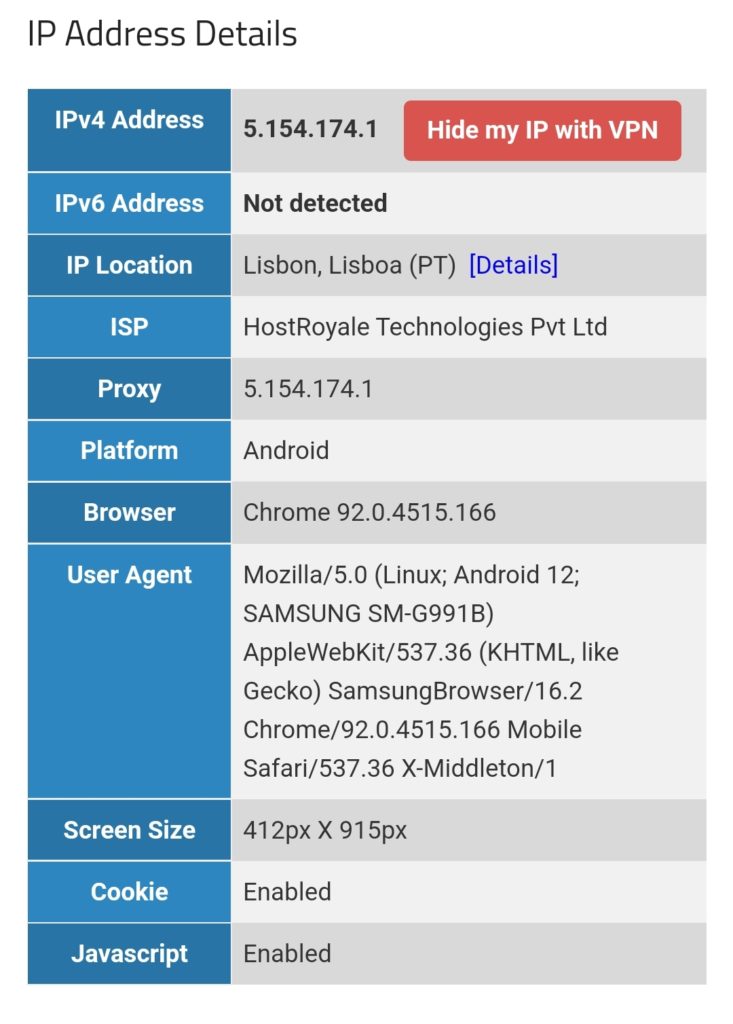
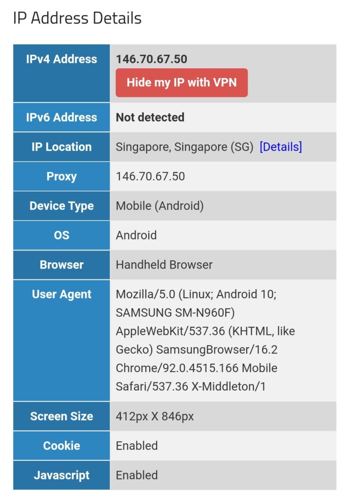
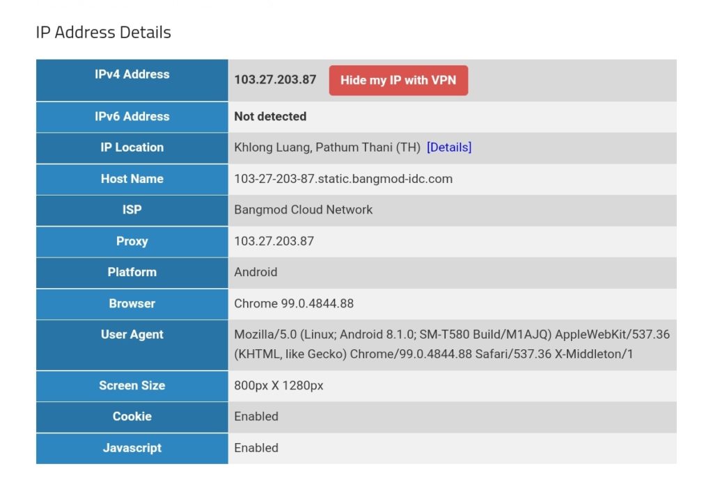
When we place the 3 devices gabriel-SM-G991B, gabriel-SM-N960F, and gabriel-SM-T580 outside the home network, either in a different WiFi network or in a mobile network and connect to the Linux server via the VPN services, then, because of the routing policy defined above, the devices will appear in:
- Portugal (gabriel-SM-G991B)
- Singapore (gabriel-SM-N960F)
- Thailand (gabriel-SM-T580)
We can test this with one of the websites that display IP geolocation, for example [13], and the result will look like this:
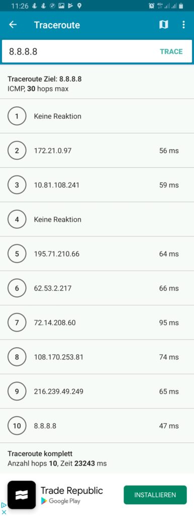
We must keep in mind that this kind of routing policy routes all outgoing traffic from the 3 devices to the respective countries, irrespective whether this is web or email or any other traffic. This is true for any protocol, and so, a traceroute to Google‘s DNS (8.8.8.8) will really go via the respective country. The images below compare the device gabriel-SM-N960F without VPN (4G mobile network) and with the VPN to the Linux server which then routes the connection via Singapore. One can easily recognize the much higher latency via Singapore. The traceroutes were taken with [14].

Policy Routing with Firewall Marking
While the ip-rule command [11] already offers a lot of possible combinations for the selection of packets, sometimes, one needs more elaborate selection criteria. This is when we use policy routing using firewall marking and the mangle table [15]. We first delete our rule set from above with the sequence:
ip rule del from 192.168.10.250/32 table Portugal priority 2000
ip rule del from 192.168.10.251/32 table Singapur priority 2000
ip rule del from 192.168.10.252/32 table Thailand priority 2000
Then, we enter new rules. Instead of using IP addresses in the selector, we use a so-called “firewall mark” (fwmark). We tell the Linux server to process packets that have a special mark in the routing tables mentioned in the action field of ip-rule:
ip rule add from all fwmark 0x1 priority 5000 lookup Portugal
ip rule add from all fwmark 0x2 priority 5000 lookup Singapur
ip rule add from all fwmark 0x3 priority 5000 lookup Thailand
But how do we mark packets? This is done in the mangle table, one of the 4 tables of the iptables [12] command. With command listed below we specify the marking of TCP packets originating from the listed IP address and going to the destination ports 80 (http) and 443 (https). All other traffic from the device with the listed IP address (e.g., smtp, imap, UDP, ICMP, …) will not be marked.
iptables -t mangle -F
iptables -t mangle -A PREROUTING -j CONNMARK --restore-mark
iptables -t mangle -A PREROUTING -m mark ! --mark 0 -j ACCEPT
iptables -t mangle -A PREROUTING -s 192.168.10.250/32 -p tcp -m multiport --dports 80,443 -m state --state NEW,RELATED -j MARK --set-mark 1
iptables -t mangle -A PREROUTING -s 192.168.10.251/32 -p tcp -m multiport --dports 80,443 -m state --state NEW,RELATED -j MARK --set-mark 2
iptables -t mangle -A PREROUTING -s 192.168.10.252/32 -p tcp -m multiport --dports 80,443 -m state --state NEW,RELATED -j MARK --set-mark 3
iptables -t mangle -A PREROUTING -j CONNMARK --save-mark
Let us have a closer look at the 7 iptables commands:
- This command flushes all chains of the mangle table so that the mangle table is empty.
- This command restores the marks of packets. Here, one must know that the mark of a packet is not stored in the packet itself, as the IP header does not contain a field for such a mark. Rather than that, the Linux Kernel keeps track of the mark and the packet it belongs to. However, when the Linux server sends out a packet to its destination, and the computer at the destination (e.g., a web server) answers with his own packets, then when these packets arrive at our Linux server, we want to mark them, too, because they belong to a data connection whose packets were initially marked and we might need the mark in order to process them correctly. Therefore, we “restore” the mark in the PREROUTING chain of the mangle table.
- This command accepts all packets that have a non-zero mark. I am not really sure if that command is needed at all (should be tested).
- This command sets the mark “1” to those packets that fulfil all these requirements:
- It comes from the source IP address 192.168.10.250.
- It uses TCP.
- It goes to one of the destination ports 80 (http) or 443 (https).
- It constitutes a NEW or RELATED connection.
- This command sets the mark “2” to those packets that fulfil all these requirements:
- It comes from the source IP address 192.168.10.251.
- It uses TCP.
- It goes to one of the destination ports 80 (http) or 443 (https).
- It constitutes a NEW or RELATED connection.
- This command sets the mark “3” to those packets that fulfil all these requirements:
- It comes from the source IP address 192.168.10.252.
- It uses TCP.
- It goes to one of the destination ports 80 (http) or 443 (https).
- It constitutes a NEW or RELATED connection.
- This command stores in the mark of the packets in the connection tracking table.
After we have entered these commands, the mangle table should look somewhat like this:
caipirinha:/etc/openvpn # iptables -t mangle -L -n -v
Chain PREROUTING (policy ACCEPT 210K packets, 106M bytes)
 pkts bytes target     prot opt in     out     source               destination
 953K  384M CONNMARK   all  --  *      *       0.0.0.0/0            0.0.0.0/0            CONNMARK restore
 177K   88M ACCEPT     all  --  *      *       0.0.0.0/0            0.0.0.0/0            mark match ! 0x0
  989 76505 MARK       tcp  --  *      *       192.168.10.250       0.0.0.0/0            multiport dports 80,443 state NEW,RELATED MARK set 0x1
 1233 82791 MARK       tcp  --  *      *       192.168.10.251       0.0.0.0/0            multiport dports 80,443 state NEW,RELATED MARK set 0x2
 1017 72624 MARK       tcp  --  *      *       192.168.10.252       0.0.0.0/0            multiport dports 80,443 state NEW,RELATED MARK set 0x3
 776K  296M CONNMARK   all  --  *      *       0.0.0.0/0            0.0.0.0/0            CONNMARK save

Chain INPUT (policy ACCEPT 203K packets, 104M bytes)
 pkts bytes target     prot opt in     out     source               destination

Chain FORWARD (policy ACCEPT 137K packets, 69M bytes)
 pkts bytes target     prot opt in     out     source               destination

Chain OUTPUT (policy ACCEPT 199K packets, 107M bytes)
 pkts bytes target     prot opt in     out     source               destination

Chain POSTROUTING (policy ACCEPT 335K packets, 176M bytes)
 pkts bytes target     prot opt in     out     source               destination
The values in the columns pkts, bytes will most probably be different in your case. They show how many IP packets and bytes have matched this rule and can help in controlling or debugging the configuration and the traffic flows.
The entries in the mangle table consequently mark the packets that traverse our Linux router and that are from one of the devices gabriel-SM-G991B, gabriel-SM-N960F, or gabriel-SM-T580 and that are destined to a web server (TCP ports 80, 443) with either the fwmark “1”, “2”, or “3”. Based on this fwmark, the packets are then sent to the routing tables Portugal, Singapur or Thailand. Using both the routing policy database and the mangle table is a powerful instrument for selecting packets and connections that shall be routed in a special way which gives us a lot of flexibility.
For example, if we only had one device to be considered (Gabriel-SM-G991B), the two command that we have issues before:
ip rule add from all fwmark 0x1 priority 5000 lookup Portugal
iptables -t mangle -A PREROUTING -s 192.168.10.250/32 -p tcp -m multiport --dports 80,443 -m state --state NEW,RELATED -j MARK --set-mark 1
have the same effect as these two commands:
ip rule add from 192.168.10.250/32 fwmark 0x1 priority 5000 lookup Portugal
iptables -t mangle -A PREROUTING -p tcp -m multiport --dports 80,443 -m state --state NEW,RELATED -j MARK --set-mark 1
In the first case, the source address selection is done in the iptables command, in the second case it is done in the ip rule command. With the 3 devices that have, the second way is not a solution as it would create the fwmark “1” on all packets that go to a web server and the subsequent entries in the mangle table would not be executed any more. We therefore have to create rules with extreme caution, in order not to jeopardize our intended routing behavior. I therefore recommend being as specific as possible already in the iptables command, also in order to avoid excessive packet marking as this complicates your life when you have to debug your setup.
When we have the setup described in this chapter active, the 3 devices (gabriel-SM-G991B, gabriel-SM-N960F, gabriel-SM-T580) will appear to be in the respective countries, similar to the setup in the previous chapter where we only modified the routing policy database. We can test this with one of the websites that display IP geolocation, for example [13], and the result will look like this:
However, if we execute a traceroute command on one of the devices, the traceroute does not go via the respective country because it uses the protocol ICMP rather than TCP and is therefore not marked and consequently is not routed via any of the client VPNs. This can be seen in the rightest image in the following gallery where a traceroute to Google‘s DNS (8.8.8.8) has been made. The traceroutes were taken with [14].
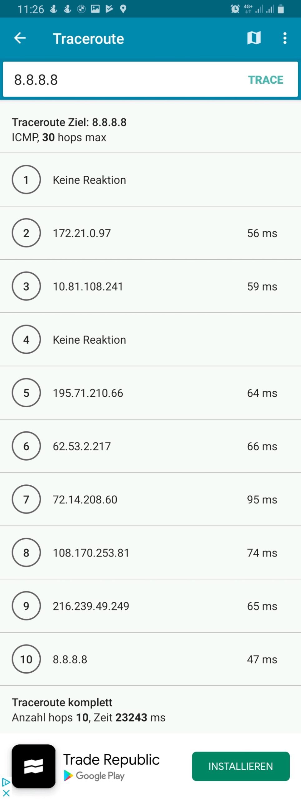
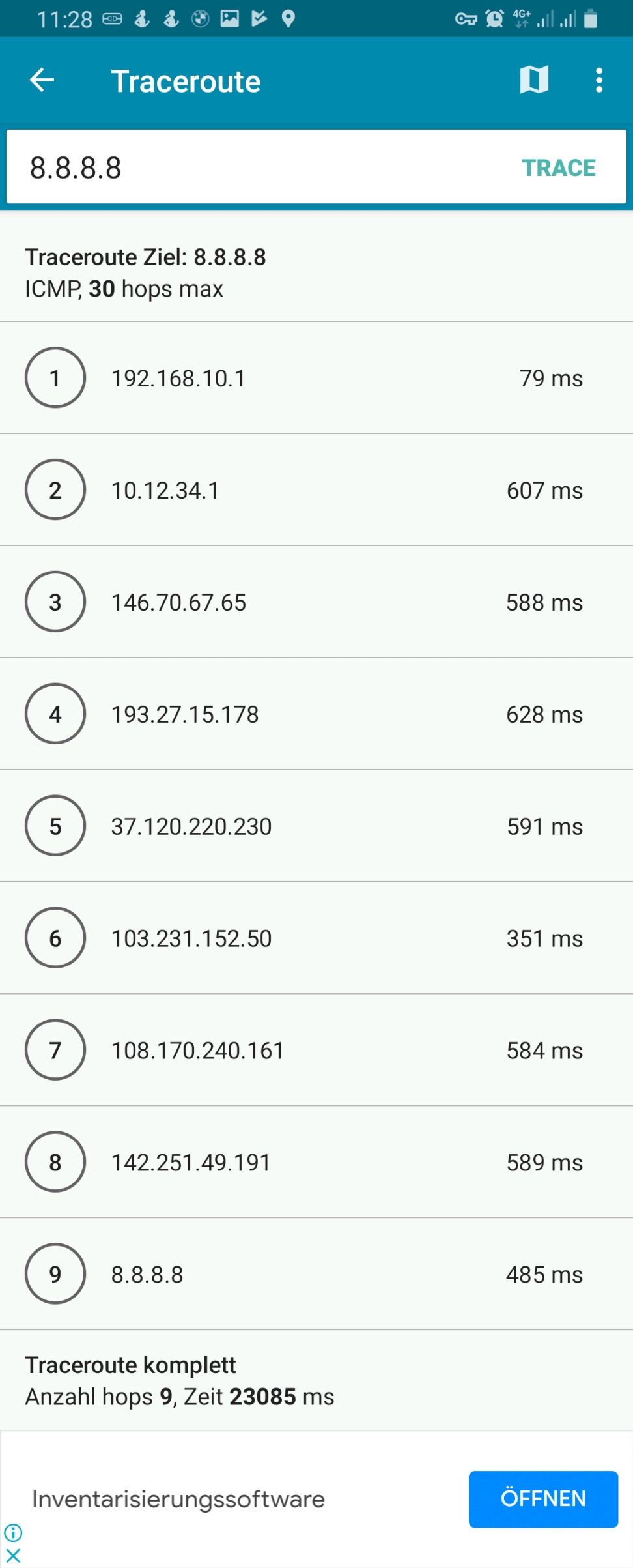

Connection Tracking
In the previous chapter, the iptables statements for the mangle table apply to NEW or RELATED connections only. Let us therefore look into the concept of connection tracking [4], [21]. This is achieved by the netfilter component [16] which is linked to the Linux Kernel keeps track of stateful connections in the connection tracking table, very similar to a stateful firewall [17]. Important states are [4]:
- NEW: The packet does not belong to an existing connection.
- ESTABLISHED: The packet belongs to an “established” connection. A connection is changed from NEW to ESTABLISHED when it receives a valid response in the opposite direction.
- RELATED: Packets that are not part of an existing connection but are associated with a connection already in the system are labeled RELATED. An example are ftp connections which open connections adjacent to the initial one [18].
- INVALID: Packets can be marked INVALID if they are not associated with an existing connection and are not appropriate for opening a new connection.
The mighty conntrack toolset [19] contains the command conntrack [20] which can be used to see the connection tracking table (actually, there are also different tables) and to inspect various behaviors around the connection tracking table. We can, for example, examine which connections have the fwmark “2” set, that is, which connections have been set up by the device Gabriel-Tablet using the source IP address 192.168.10.251:
caipirinha:/etc/openvpn # conntrack -L -m2
tcp      6 431952 ESTABLISHED src=192.168.10.251 dst=172.217.19.74 sport=38330 dport=443 src=172.217.19.74 dst=10.12.42.37 sport=443 dport=38330 [ASSURED] mark=2 use=1
tcp      6 431832 ESTABLISHED src=192.168.10.251 dst=34.107.165.5 sport=38924 dport=443 src=34.107.165.5 dst=10.12.42.37 sport=443 dport=38924 [ASSURED] mark=2 use=1
tcp      6 431955 ESTABLISHED src=192.168.10.251 dst=142.250.186.170 sport=58652 dport=443 src=142.250.186.170 dst=10.12.42.37 sport=443 dport=58652 [ASSURED] mark=2 use=1
tcp      6 65 TIME_WAIT src=192.168.10.251 dst=142.250.185.66 sport=57856 dport=443 src=142.250.185.66 dst=10.12.42.37 sport=443 dport=57856 [ASSURED] mark=2 use=1
tcp      6 431954 ESTABLISHED src=192.168.10.251 dst=142.250.186.170 sport=58640 dport=443 src=142.250.186.170 dst=10.12.42.37 sport=443 dport=58640 [ASSURED] mark=2 use=1
conntrack v1.4.5 (conntrack-tools): 5 flow entries have been shown.
Each line contains a whole set of information which is explained in detail in [2], § 7. For a quick orientation, we have to know the following points:
- Each line has two parts. The first part lists the IP header information of the newly initiated connection; in our case, we observe:
- The source IP address is always 192.168.10.251 (Gabriel-Tablet).
- The destination port is either 80 or 443 as we change the routing for exactly these destination ports only
- The second part lists the IP header information of the expected or received (as an answer) packets, and, we observe:
- The source IP address of the answering packet is the destination IP address of the initiating packet which makes sense.
- The source port of the answering packet is the destination port of the initiating packet which again makes sense.
- The destination IP address of the answering packet is not 192.168.10.251, but 10.12.42.37. This is because 10.12.42.37 is the IP address of the tun1 device of the Linux server. When we send out the initiating packet from 192.168.10.251, the packet will go to the Linux server who acts as router. In the server, the packet will be changed, and the server will use its source address on the outgoing interface tun1 as source address on the packet as the remote end point of the client VPN connection that we use would not know how to route a packet to 192.168.10.251 (the remote end point does not know anything of the network 192.168.10.0/24 on our side).
- [ASSURED] means that the connection has already seen traffic in both directions, the connections has therefore been set up successfully.
- Coincidentally, in our example, we only have TCP connections; however, the connection tracking table can also comprise UDP or ICMP connections.
The command conntrack [20] offers much more opportunities and even allows to change entries in the connection tracking table. So, we barely scratched the surface.
Conclusion
In this blog post, we have used client VPN connections to execute some experiments on policy routing in which we make different devices appear to be located in different countries. We touched the concepts of routing tables, the routing policy database, the mangle table, and the connection tracking table. The possibilities of all these items go far beyond of what we discussed in this blog post. The interested reader is referred to the sources listed below to get in-depth knowledge and to understand the vast possibilities that these items offer to the expert.
Sources
- [1] = Linux Advanced Routing & Traffic Control HOWTO
- [2] = Iptables Tutorial 1.2.2
- [3] = Guide to IP Layer Network Administration with Linux
- [4] = A Deep Dive into Iptables and Netfilter Architecture
- [5] = Policy Routing With Linux – Online Edition
- [6] = Understanding modern Linux routing (and wg-quick)
- [7] = Netfilter Connmark
- [8] = Internet Censorship in China
- [9] = Reference manual for OpenVPN 2.4
- [10] = man 8 wg-quick
- [11] = man 8 ip-rule
- [12] = man 8 iptables
- [13] = Where is my IP location? (Geolocation)
- [14] = PingTools Network Utilities [Google Play]
- [15] = Mangle table for iptables
- [16] = The netfilter.org project
- [17] = Stateful firewall [Wikipedia]
- [18] = Active FTP vs. Passive FTP, a Definitive Explanation
- [19] = The conntrack-tools user manual
- [20] = man 8 conntrack
- [21] = Connection tracking