Getting around Carrier-grade NAT
Executive Summary
This blog post explains how a small internet-based shared server (“vServer”, “VPS”) can be used to tunnel connections from the internet back to a SoHo-based router that does not have a publicly routable IPv4 internet address, maybe because the internet service provider (ISP) uses Carrier-grade NAT (CG-NAT) and only offers “real” IPv4 addresses at cost. As internet-based shared servers can be rented for small fees, the approach described below is a viable concept to overcome the limitations of CG-NAT connections which might only allow outgoing connections for IPv4 or even for both IPv4 and IPv6. This concept can even be used if the SoHo server is connected via the mobile network to the internet-based shared server.
Background
The implementation proved useful for me when I switched from my DSL ISP who happily had provided me with “real” (routable) IPv4 and IPv6 addresses to a new fiber-optics ISP that provides IPv6, but that uses CG-NAT on IPv4 so that no incoming IPv4 connections are possible from the internet. As I feared that my server at home would only be accessible from the internet via IPv6, I had to develop this counterstrategy.
Preconditions
In order to use the approach described here, you should:
- … have access to a Linux machine which is already properly configured for dual stack on its principal network interface (e.g., eth0)
- … additionally have access to a cloud-based Linux server which is already properly configured for dual stack on its principal network interface
- … have access to a DNS resolver where you can enter an IPv4 and an IPv6 addresses for your SoHo server so that your domain resolves properly
- … have the package openvpn installed on both machines (preferably from a repository of your Linux distribution)
- … know how to create client and server certificates for openvpn [1]
- … have knowledge of routing concepts, networks, some understanding of shell scripts and configuration files
- … know related system commands like sysctl
- … familiarize yourself with [2], [3], [4], [5]
Description and Usage
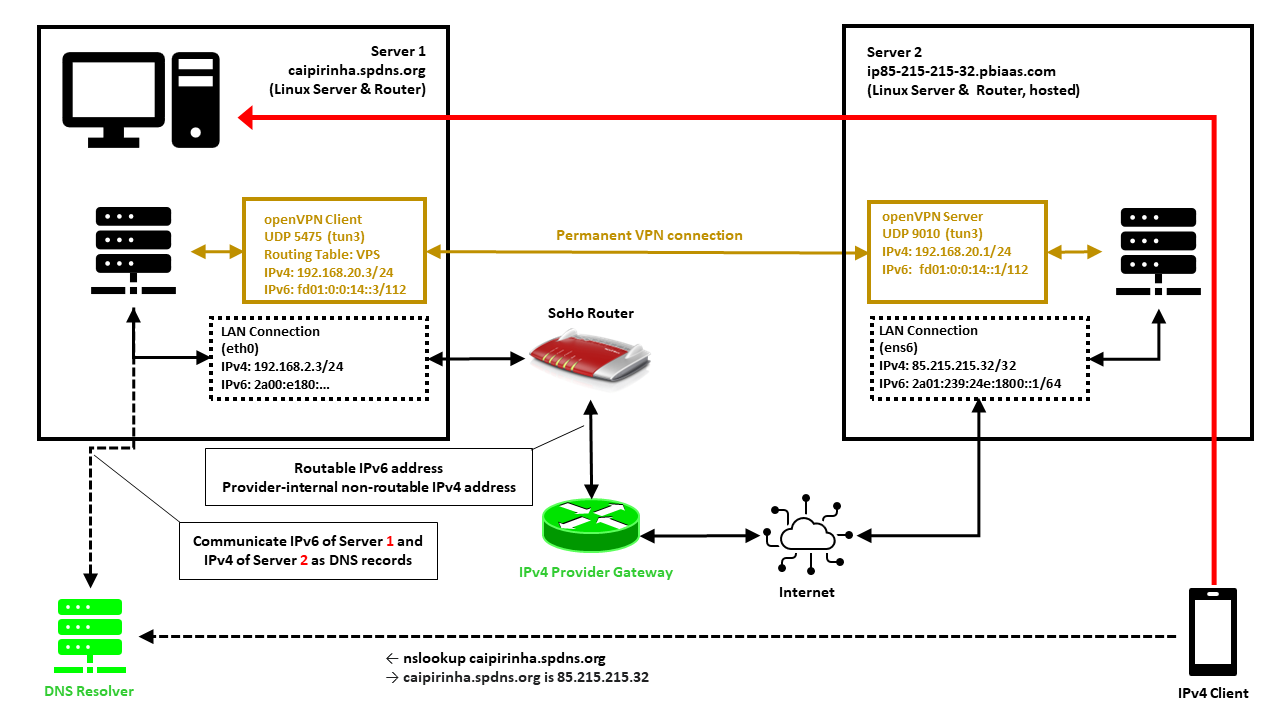
In this setup, we have a full-blown SoHo server (Server 1) which is hosting numerous services that we want to offer to the world. However, while the provider allocates an IPv6 /64 subnet, he does not offer an IPv4 address that would be reachable from the internet. Rather than that, he employs Carrier-grade NAT (CG-NAT) for IPv4. This is a typical setup for fiber-optics or cable providers or for mobile network providers. In some countries (which came late to the internet), IPv4 addresses are scarce in general, and so you might experience CG-NAT for all private internet connections.
This is where Server 2 comes into play. Server 2 is a hosted shared server, it just needs a good internet connection and a fixed IPv4 address, but it does not need a lot of computational power. It will only be used to forward traffic to Server 1. In my case, I rented a small “VPS” server from Ionos as I personally found their offer compelling [6], but there are alternatives. My VPS has a dual-stack and a fixed IPv4 address and a fixed IPv6 /64 subnet allocated. The IPv4 address of the VPS is 85.215.215.32, and we will use this IPv4 address as entry address for our SoHo server (Server 1) caipirinha.spdns.org.
A new Routing Table
We want to separate the traffic that we receive and send out in return via the VPN network (192.168.20.0/24) from the regular traffic that enters and leaves the server via the network 192.168.2.0/24. Therefore, we set up a new routing table as described in [7] and name it “VPS”. In order to access it via its name, we modify /etc/iproute2/rt_tables:
#
# reserved values
#
255 local
254 main
253 default
0 unspec
#
# local
#
#1  inr.ruhep

...
201 VPS
...
Setting up a permanent VPN
First, we need to set up a permanent VPN connection from Server 1 to Server 2. Server 1 will be the VPN client, and Server 2 will be the VPN server. I chose this direction because in that approach, Server 1 may even be connected to the internet via a mobile only connection CG-NAT both on IPv4 and IPv6. In my approach, I use the network 192.168.20.0/24 for the VPN connection; Server 1 gets the address 192.168.20.3 and Server 2 gets the address 192.168.20.1.
Server 2: The VPN Server
On Server 2, we set up a VPN server listening on port 9010 (UDP), using dev tun3. The configuration file is shown below. In my case, Server 2 is an Ubuntu-based server, and so it is recommended to adjust the settings in the configuration file /etc/default/openvpn which governs the behavior of openvpn connections on Ubuntu. I modified this configuration file so that only one openvpn service is started. This is done via the configuration option
AUTOSTART="server-9010"For the configuration of the server side, I meanwhile include the CA certificate, the server certificate and the private key in one configuration file. I find that more convenient, but it certainly may have disadvantages, The key message is that it is possible to do so. My own certificates and private keys have been substituted by “…” here, of course.
# Konfigurationsdatei für den openVPN-Server auf IONOS VPS (UDP:9010)

client-config-dir     /etc/openvpn/server/conf-9010
crl-verify            /etc/openvpn/server/crl.pem
dev                   tun3
dh                    /etc/openvpn/server/dh.pem
hand-window           90
ifconfig              192.168.20.1  255.255.255.0
ifconfig-pool         192.168.20.2  192.168.20.254  255.255.255.0
ifconfig-ipv6         fd01:0:0:14::1 2a01:239:24e:1800::1
ifconfig-ipv6-pool    fd01:0:0:14::2/112
ifconfig-pool-persist /etc/openvpn/server/ip-pool-9010.txt
keepalive             20 80
log                   /var/log/openvpn/server-9010.log
mode                  server
persist-key
persist-tun
port                  9010
proto                 udp6
reneg-sec             86400
script-security       2
status                /var/run/openvpn/status-9010
tls-server
topology              subnet
verb                  1
writepid              /var/run/openvpn/server-9010.pid

# Topologie des VPN und Default-Gateway
push "topology subnet"
push "tun-ipv6"

<ca>
-----BEGIN CERTIFICATE-----
...
-----END CERTIFICATE-----
</ca>

<cert>
-----BEGIN CERTIFICATE-----
...
-----END CERTIFICATE-----
</cert>

<key>
-----BEGIN PRIVATE KEY-----
...
-----END PRIVATE KEY-----
</key>
We also must take care that our client always gets the IP address 192.168.20.3 as we originally envisioned. This is done with the client-specific configuration file /etc/openvpn/server/conf-9010/caipirinha_client:
# Spezielle Konfigurationsdatei für den Server caipirinha.spdns.org als Client
#

ifconfig-push      192.168.20.3 255.255.255.0
ifconfig-ipv6-push fd01:0:0:14::3/111 fd01:0:0:14::1
The client-specific configuration file additionally also allocates the static IPv6 address fd01:0:0:14::3 to our client. Finally, the service can then be started with:
systemctl start openvpn@server-9010.serviceServer 1: The VPN Client
On Server 1, we set up a VPN client using dev tun3. The local port shall always be 5475 (arbitrarily chosen but fixed so that we can track the connection easily if necessary). Server 2 is addressed via its public IPv6 address (2a01:239:24e:1800::1), but we could also have used its public IPv4 address (85.215.215.32). I chose the IPv6 address because the IPv4 connection would run via the provider gateway, and that might slow down the connection or make it less reliable.
# Konfigurationsdatei für den openVPN-Client auf caipirinha.spdns.org zum IONOS-Server

client
dev              tun3
explicit-exit-notify
hand-window      90
keepalive        10 60
log              /var/log/openvpn_ionos_vpn.log
lport            5475
persist-key
persist-tun
proto            udp
remote           2a01:239:24e:1800::1 9010
remote-cert-tls  server
remote-random
reneg-sec        86400
route-nopull
script-security  2
status           /var/run/openvpn/status_ionos_vpn
up               /etc/openvpn/start_piavpn.sh
verb             1

<ca>
-----BEGIN CERTIFICATE-----
...
-----END CERTIFICATE-----
</ca>

<cert>
-----BEGIN CERTIFICATE-----
...
-----END CERTIFICATE-----
</cert>

<key>
-----BEGIN PRIVATE KEY-----
...
-----END PRIVATE KEY-----
</key>
One peculiarity is the referenced script /etc/openvpn/start_piavpn.sh. At the start of the VPN connection, this script populates the routing table VPS:
#!/bin/bash
#
# This script requires the tool "ipcalc" which needs to be installed on the target system.

# Set the correct PATH environment
PATH='/sbin:/usr/sbin:/bin:/usr/bin'

VPN_DEV=$1
VPN_SRC=$4
VPN_MSK=$5

VPN_GW=$(ipcalc ${VPN_SRC}/${VPN_MSK} | sed -n 's/^HostMin:\s*\([0-9]\{1,3\}\.[0-9]\{1,3\}\.[0-9]\{1,3\}\.[0-9]\{1,3\}\).*/\1/p')
VPN_NET=$(ipcalc ${VPN_SRC}/${VPN_MSK} | sed -n 's/^Network:\s*\([0-9]\{1,3\}\.[0-9]\{1,3\}\.[0-9]\{1,3\}\.[0-9]\{1,3\}\/[0-9]\{1,2\}\).*/\1/p')

case "${VPN_DEV}" in
  "tun0") ROUTING_TABLE='Portugal';;
  "tun1") ROUTING_TABLE='Brasilien';;
  "tun2") ROUTING_TABLE='Singapur';;
  "tun3") ROUTING_TABLE='VPS';;
  "tun8") ROUTING_TABLE='China';;
esac

...

ip route add ${VPN_NET} dev ${VPN_DEV} proto static scope link src ${VPN_SRC} table ${ROUTING_TABLE}
ip route replace default dev ${VPN_DEV} via ${VPN_GW} table ${ROUTING_TABLE}
When the VPN connection is stopped, then the VPN network and the default route are automatically deleted from the routing table VPS as the VPN network collapses. While the VPN connection is up, we can view the routing table VPS with:
caipirinha:~ # ip route list table VPS
default via 192.168.20.1 dev tun3
192.168.20.0/24 dev tun3 proto static scope link src 192.168.20.3
Finally, the client can be started with:
systemctl start openvpn@client_ionos_vps.serviceOf course, the actual name after “openvpn@” in this command depends on how you named the respective client configuration file.
Channeling the Traffic
Now, we must make sure that traffic that is received by Server 2 and that shall be forwarded to Server 1 is channeled in an appropriate way through the VPN connection. We need to execute some commands on both servers. [3], [4] explain how that can be achieved.
Server 2: Forward the traffic
We need to enable IPv4 routing and simply forward connections to those ports where we offer our service on Server 1. This is done by:
sysctl -w net.ipv4.ip_forward=1

iptables -t nat -A PREROUTING -p tcp -m multiport --dports 20,21,25,80,443,465,587,873,993,3000,4078:4088,8009,8080:8082 -j DNAT --to-destination 192.168.20.3
iptables -t nat -A PREROUTING -p udp -m multiport --dports 1194,2372:2380,4396,44576 -j DNAT --to-destination 192.168.20.3
We need two iptables commands, one for TCP connections and one for UDP connections. Both are located in the PREROUTING chain. As we can see, we can combine various ports and even port ranges that shall be forwarded in one command, that is very handy. Of course, you should only forward the ports that correspond to services on Server 1 that you want to offer to the world. It is also possible to offer the services on different ports on Server 2, so that http is listening on port 81 TCP rather than on 80 TCP although in my opinion, that does not make much sense.
Let us assume that a client initiates a connection to Server 2 on port 80 (http). The first iptables command changes the destination IP from the IP address of Server 2 (85.215.215.32) to the IP address 192.168.20.3 which is the VPN client on Server 1. As we have enabled routing on Server 2, the packet is routed from ens6 to tun3 and leaves Server 2 via the VPN connection to Server 1.
Server 1: Accept the traffic in Routing Table VPS
Server 1 receives the traffic and needs to channel it via routing table VPS. This is done with the command:
ip rule add from 192.168.20.3 priority 1000 table VPSThe beauty of this command is that the outgoing traffic will also use table VPS and therefore leave Server 1 not via the default interface eth0 to the SoHo router, but via tun3 back to Server 2 (see [4], [8]). We can identify the traffic that we receive from Server 2 at Server 1 with the conntrack command:
caipirinha:~ # conntrack -L | fgrep "192.168.20"
tcp      6 117 TIME_WAIT src=109.250.125.241 dst=192.168.20.3 sport=55370 dport=80 src=192.168.20.3 dst=109.250.125.241 sport=80 dport=55370 [ASSURED] mark=0 use=1
tcp      6 117 TIME_WAIT src=109.250.125.241 dst=192.168.20.3 sport=55366 dport=80 src=192.168.20.3 dst=109.250.125.241 sport=80 dport=55366 [ASSURED] mark=0 use=1
tcp      6 117 TIME_WAIT src=109.250.125.241 dst=192.168.20.3 sport=55368 dport=80 src=192.168.20.3 dst=109.250.125.241 sport=80 dport=55368 [ASSURED] mark=0 use=1
In that case, we have observed a https request (dport=80) from the source IP 109.250.125.241 which has been tunneled via our VPN from Server 2 to Server 1. The client (represented by a mobile phone in the image above) has basically access Server 2 along the red arrow drawn in the image. The benefit of the concept described here is also that the source address (here: 109.250.125.241) is not concealed and therefore, filtering can be done on Server 1 with iptables as if Server 1 was accessed directly. Furthermore, the correct client IP address is in the respective log files.
Other approaches which use SNAT on Server 2 would conceal the source address of the client and therefore, such filtering would have to occur on Server 2 already. The logs on Server 1 however would contain 192.168.20.1 as sole source address for all incoming connections which is why such an approach is not suitable.
Updating the DNS Server
Now we should spend some thoughts on the domain name resolution of Server 1. In my case, I already had a script that communicated any change of the IP address of Server 1 provoked by the ISP almost on a daily basis to a Dynamic DNS (DDNS) provider which so far has done the name resolution for clients that want to access Server 1. I use my own script, but most DDNS providers also offer pre-written scripts for certain architectures or routers.
In our concept though, we must communicate the IPv6 address of Server 1 and the IPv4 address of Server 2 to our DDNS service. As Server 2 has a static IPv4 address, adapting any script should be easy. Alternatively, one could limit the script to only update the IPv6 address of Server 1 and enter the static IPv4 address via the web-based user interface of the DDNS hoster.
Conclusion
This blog post shows how we can channel back traffic via a small internet-based server to a powerful server that is connected via CG-NAT and that may therefore not be accessible directly from the internet. With the approach described here, Server 1 can even be located in a mobile network or inside a firewalled environment as long as the firewall permits outgoing openvpn connections.
Sources
- [1] = Setting up your own Certificate Authority (CA) and generating certificates and keys for an OpenVPN server and multiple clients
- [2] = Setting up Dual Stack VPNs
- [3] = iptables – Port forwarding over OpenVpn
- [4] = Routing for multiple uplinks/providers
- [5] = Predictable Network Interface Names
- [6] = vServer Günstig Mieten » VPS ab 1€ / M.
- [7] = Setting up Client VPNs, Policy Routing
- [8] = Two Default Gateways on One System